2-3
1
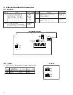
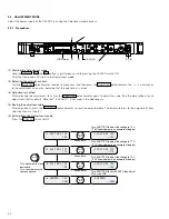
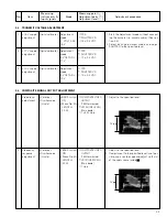
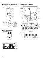
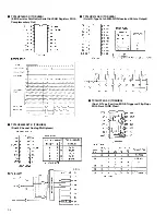
+15 V supply
adjustment
Digital voltmeter
Adjustment
mode
1: VOLT ADJ
15 V
1. Start the Adjustment mode without connect-
ing the camera (i.e. camera cable). (See sec-
tion 2.2.)
2. Select each adjustment mode and adjust
SHUTTER to the specified level.
*
TP9
-
SHUTTER VR
+
15 ± 0.2 VDC
Measuring
Measuring point (
*
)
No.
Item
instruments &
Mode
Adjustment parts (
-
)
Adjustment procedure
Input signals
Adjustment level (
+
)
2.3
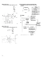
TRANSMIT VOLTAGE ADJUSTMENT
2
+17 V supply
adjustment
Digital voltmeter
Adjustment
mode
2: VOLT ADJ
17 V
*
TP9
-
SHUTTER VR
+
17 ± 0.2 VDC
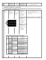
3
+19 V supply
adjustment
Digital voltmeter
Adjustment
mode
3: VOLT ADJ
19 V
*
TP9
-
SHUTTER VR
+
19 ± 0.2 VDC
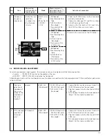
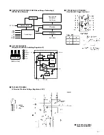
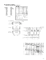
1
Video level
adjustment
• Color bar
• Oscilloscope
(H-rate)
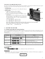
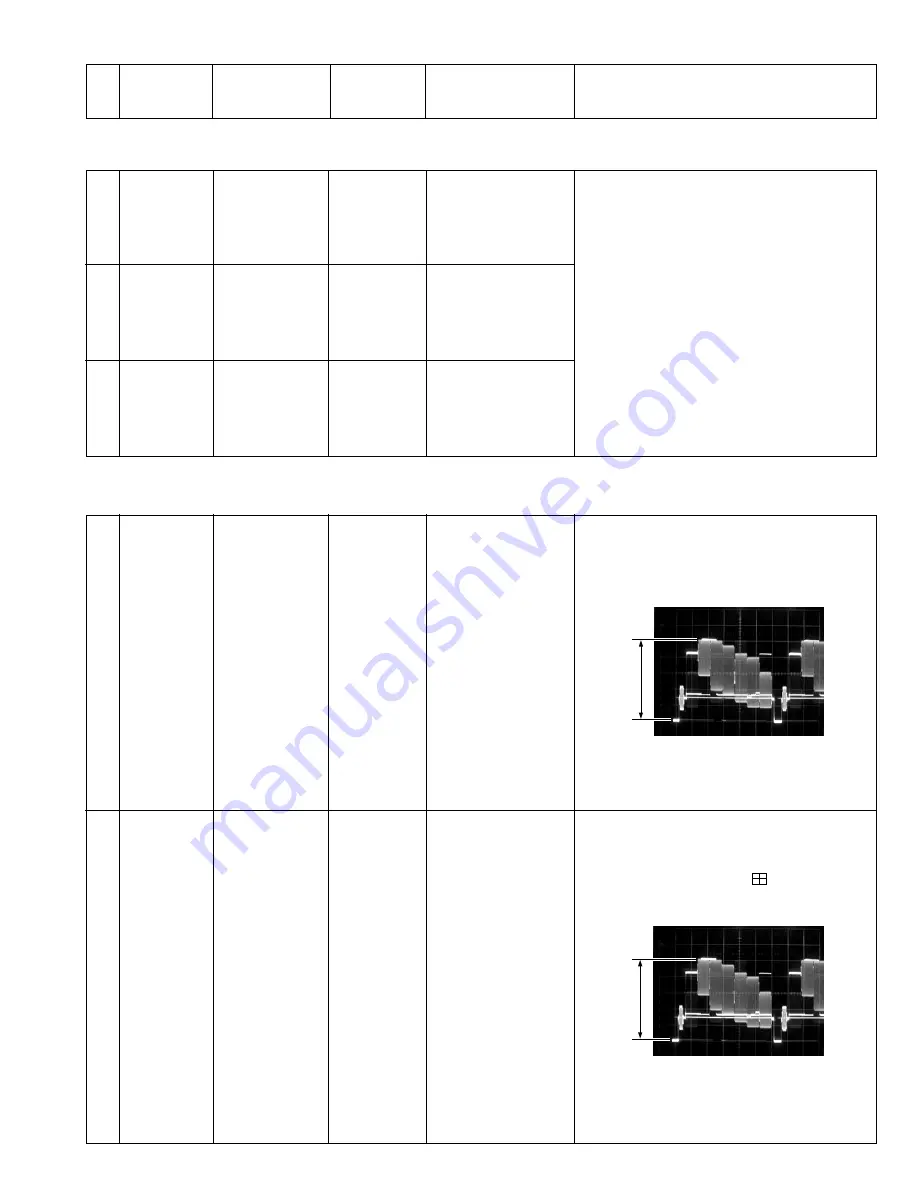
1. Adjust to the specified level.
*
COMPOSITE VIDEO
OUTPUT
(75
Ω
terminated)
-
VR102 (IRIS LEVEL)
[Main board]
+
1 ± 0.03 Vp-p
2.4
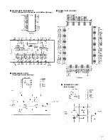
COMPOSITE SIGNAL OUTPUT ADJUSTMENT
2
Frequency
response
adjustment
1. Adjust to the specified level.
2. If adjustment to the specified level is not pos-
sible, use a vectorscope and adjust so that all
of the spots come inside
.
• Color bar
• Oscilloscope
(H-rate)
*
COMPOSITE VIDEO
OUTPUT
(75
Ω
terminated)
-
VR101 (VBS FREQ)
[Main board]
+
1 Vp-p
1 Vp-p
1 Vp-p
• BARS swtch:
ON
• Menu No. 2A
LENGTH:
20 M
• BARS swtch:
ON
• Menu No. 2A
LENGTH:
20 M


