
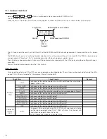
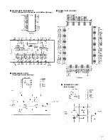
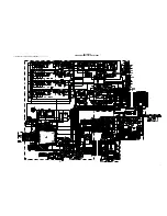
2-4
1
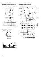
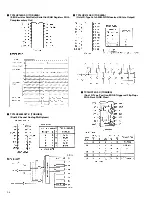
Level
adjustment
• Color bar
generator
• Oscilloscope
(H-rate)
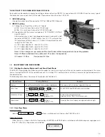
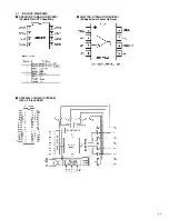
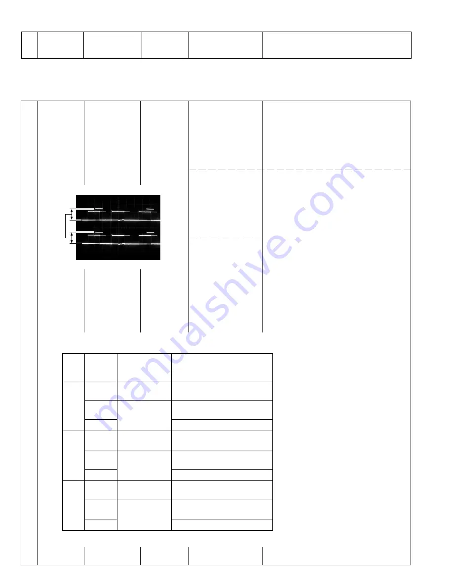
1. Connect oscilloscope CH1 and CH2 as shown
in the Measuring Point Table.
2. Adjust so that the CH1 and CH2 levels are
same levels.
• R Channel
*
See Measuring Point
Table.
-
VR201 (R LEVEL)
[Main board]
+
Same level
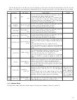
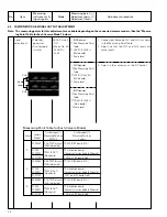
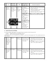
Measuring
Measuring point (
*
)
No.
Item
instruments &
Mode
Adjustment parts (
-
)
Adjustment procedure
Input signals
Adjustment level (
+
)
2.5
COMPONENT/RGB SIGNAL OUTPUT ADJUSTMENT
3. Adjust in the same way as the R Channel.
• G Channel
*
See Measuring Point
Table.
-
VR301 (G LEVEL)
[Main board]
+
Same level
• B Channel
*
See Measuring Point
Table.
-
VR401 (B LEVEL)
[Main board]
+
Same level
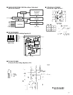
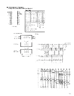
Note: The measuring points for this adjustment are variable depending on the connected camera models. (See the “Measur-
ing Point Table for Each Camera Model” below.)
Channel
Camera
Model
Oscilloscope CH1
Measuring Points on
RM-P210
Oscilloscope CH2
Measuring Points on
Camera
R
GY-DV550
R OUTPUT terminal
(75
Ω
terminated)
TP402 (R) [SE board: B-1D]
KY-D29
KY-D29W
TP202 (R OUT)
[Main board]
TP2 (Extension board)
[Connect extension board to SE board.]
KY-27C/19
CN31 pin 7 [SE board: A-6B]
G
GY-DV550
G OUTPUT terminal
(75
Ω
terminated)
TP202 (G) [SE board: B-1D]
KY-D29
KY-D29W
TP302 (G OUT)
[Main board]
TP4 (Extension board)
[Connect extension board to SE board.]
KY-27C/19
CN31 pin 6 [SE board: A-6B]
B
GY-DV550
B OUTPUT terminal
(75
Ω
terminated)
TP302 (B) [SE board: B-1D]
KY-D29
KY-D29W
TP402 (B OUT)
[Main board]
TP5 (Extension board)
[Connect extension board to SE board.]
KY-27C/19
CN31 pin 4 [SE board: A-6B]
Measuring Point Table for Each Camera Model
Same
level
CH1
CH2
• BARS swtch:
ON
• Menu No. 2A
LENGTH:
20 M


