RS-WP1WT
1-12
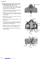
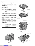
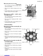
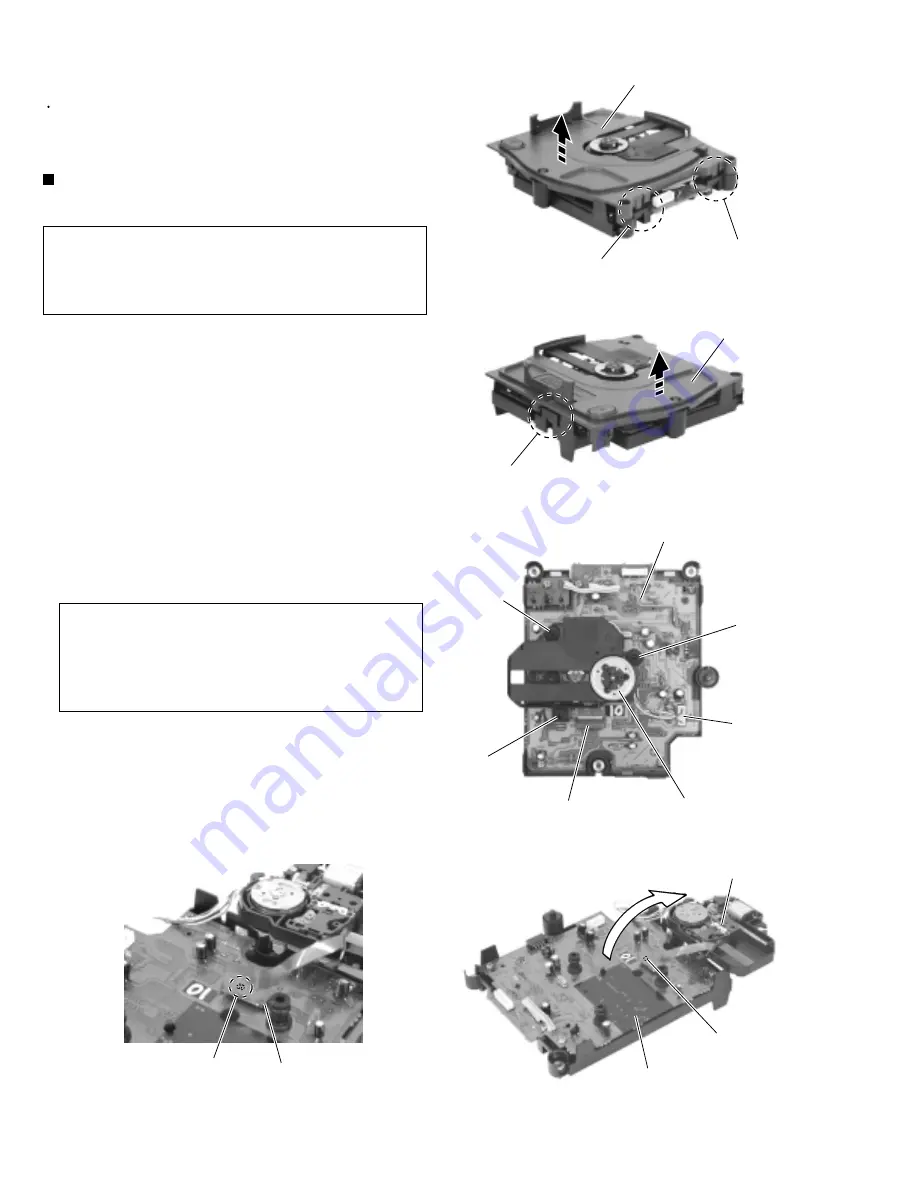
Release the three joint hooks
d
retaining the CD
mechanism cover.
Disconnect the wire from connector CN612 on the
CD servo board.
Remove the CD mechanism assembly from the three
dampers.
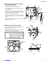
Solder the flexible wire connected to connector
CN611 on the CD servo board to the short circuit
land under the flexible wire.
After soldering, disconnect the pickup wire from
connector CN611.
1.
2.
3.
4.
Removing the CD mechanism assembly
(See Fig.22 to 26)
Prior to disconnecting the flexible wire
extending from the pickup, solder it to the
short circuit land to prevent damage to the
pickup.
CAUTION:
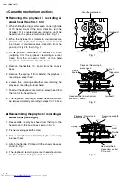
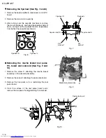
Prior to performing the following procedures, remove
the rear panel assembly and the CD mechanism
assembly section.
<CD mechanism assembly section>
When reassembling, connect the pickup
wire extending from the pickup to
connector CN611 on the CD servo
board. Then unsolder the wire soldered
to the short circuit land.
CAUTION:
Fig.22
Fig.23
Fig.24
Fig.25
Fig.26
CD mechanism cover
Joint hook d
Joint hook d
Joint hook d
CD mechanism cover
CD servo board
Damper
Damper
Damper
CD servo assembly
CN612
CN611
CD mechanism assembly
(Pickup)
CD mechanism board
Pickup wire
(Short circuit land)
CN611
Short circuit land
Summary of Contents for RS-WP1WT
Page 37: ...RS WP1WT 3 2 M E M O ...
Page 57: ...RS WP1WT 2 4 ...
Page 66: ...RS WP1WT 2 13 Tuner Board Block No 04 ...
Page 68: ...RS WP1WT 2 15 ...

