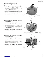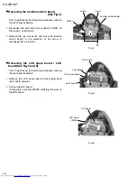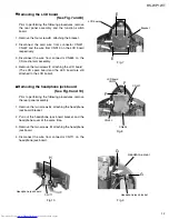
RS-WP1WT
1-13
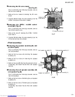
Prior to performing the following procedure, remove
the CD servo assembly.
Remove the four screws
S
retaining the CD servo
board.
Unsolder FW616 where the wire extending from the
OPEN / CLOSE switch board is soldered.
1.
2.
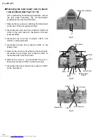
Removing the CD servo board
(See Fig.27)
Prior to performing the following procedure, remove
the CD mechanism cover.
Remove the screw
T
retaining the OPEN / CLOSE
switch board.
Unsolder FW626 where the wire extending from the
CD mechanism board is soldered.
1.
2.
Removing the OPEN / CLOSE switch
board (See Fig.27)
Prior to performing the following procedure, remove
the front assembly.
Remove the four screws
U
attaching the speaker
assembly (R).
Remove the four screws
V
attaching the speaker
assembly (L).
Remove the screw
W
attaching the speaker terminal.
If necessary, disconnect the wire from each speaker
terminal.
1.
2.
3.
Removing the speaker assembly (R) and
(L) (See Fig.28)
Prior to performing the following procedure, remove
the front assembly.
Remove the four screws
X
attaching the sub speaker
assembly (R).
Remove the four screws
Y
attaching the sub speaker
assembly (L).
If necessary, disconnect the wire from each speaker
terminal.
1.
2.
Removing the sub speaker assembly (R)
and (L) (See Fig.28)
<Front assembly>
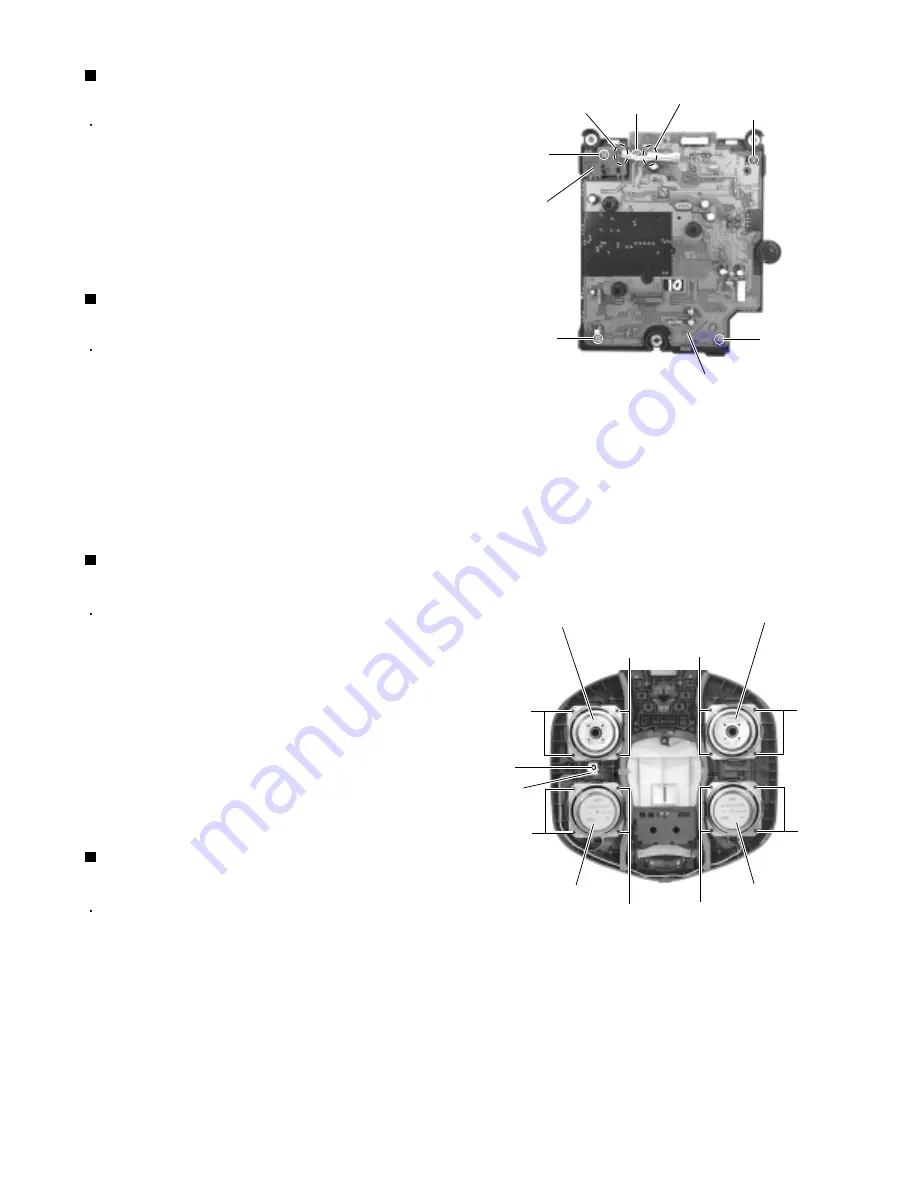
Fig.27
Fig.28
OPEN / CLOSE
switch board
FW626
FW616
CD mechanism board
S
S
S
S
T
Sub speaker assembly (R)
Sub speaker assembly (L)
Speaker assembly (R)
Speaker assembly (L)
Y
X
W
U
V
U
V
X
Y
Speaker
terminal
Summary of Contents for RS-WP1WT
Page 37: ...RS WP1WT 3 2 M E M O ...
Page 57: ...RS WP1WT 2 4 ...
Page 66: ...RS WP1WT 2 13 Tuner Board Block No 04 ...
Page 68: ...RS WP1WT 2 15 ...

