RS-WP1WT
1-32
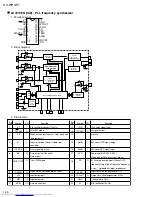
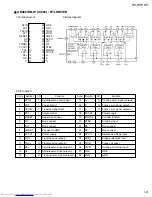
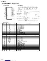
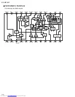
AN8838SB(IC604) : RF & Servo AMP
1. Terminal layout
2. Block diagram
3. Pin function
1
VCC
2
POA
3
POC
4
POB
5
POD
6
RFFB
7
RF
8
RF IN
9
LPD
10
LD
11
CSBRT
12
CEA
13
BDO
14
GND
28 PDF
27 PDE
26 VREF
25 TEOUT
24 TEN
23 TBAL
22 FBAL
21 FEN
20 FEOUT
19 ENV
18 LDON
17 OFTR
16 PDOWN
15 RFDET
1
2
3
4
5
6
7
8
9
10
11
12
13
14
15
16
17
18
19
20
21
22
23
24
25
26
27
28
Pin No.
Symbol
I/O
Descriptions
VCC
POA
POC
POB
PO
RFFB
RF
RF IN
LPD
LD
CSBRT
CEA
BDO
GND
RFDET
PDOWN
OFTR
LDON
ENV
FEOUT
FEN
FBAL
TBAL
TEN
TEOUT
VREF
PDE
PDF
Power supply
Focus signal input A
Focus signal input C
Focus signal input B
Focus signal input D
RFamp input
RFamp output
RF input
APC amp input terminal
APC amp output terminal
OFF Track External terminal
A capacitor is connected to this terminal detect the envelope of RF
signal
BDO output
Connect to GND
RF detect signal input
Power down input
OFF Track output
APC ON/OFF control terminal
Envelope output
Output pin of focus error
Focus error amp output
Focus balance control
Tracking balance control
Tracking error output
Tracking error signal output
Reference voltage output
I-V amp input
I-V amp input
-
I
I
I
I
I
O
I
I
O
I
I/O
O
-
I
I
O
I
O
O
I
I
I
O
O
O
I
I
Summary of Contents for RS-WP1WT
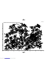
Page 37: ...RS WP1WT 3 2 M E M O ...
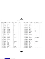
Page 57: ...RS WP1WT 2 4 ...
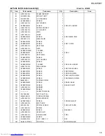
Page 66: ...RS WP1WT 2 13 Tuner Board Block No 04 ...
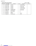
Page 68: ...RS WP1WT 2 15 ...

