RS-WP1WT
1-5
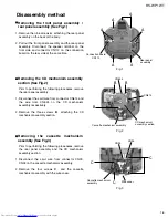
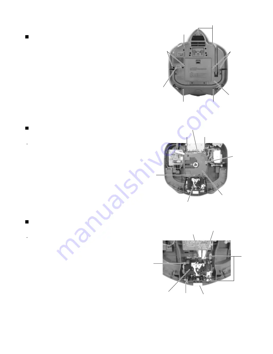
Remove the nine screws
A
attaching the rear panel
assembly on the back of the body.
Pull out the front panel assembly and the rear panel
assembly. Disconnect the speaker terminal on the
front side and connector CN112 on the connection
board on the rear side at the same time.
1.
2.
Disassembly method
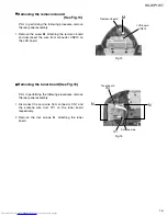
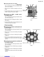
Removing the front panel assembly /
rear panel assembly (See Fig.1)
Prior to performing the following procedures, remove
the rear panel assembly.
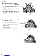
Disconnect the card wire from connector CN614 and
the wire from CN624 on the CD mechanism
assembly respectively.
Remove the three screws
B
attaching the CD
mechanism assembly section.
1.
2.
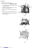
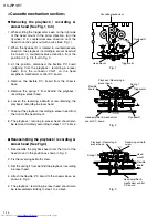
Removing the CD mechanism assembly
section (See Fig.2)
Prior to performing the following procedures, remove
the rear panel assembly and the CD mechanism
assembly section.
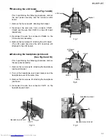
Disconnect the card wire from connector CN33,
CN34 on the cassette mechanism assembly.
Remove the four screws
C
and the cassette
mechanism assembly with the wire cover.
1.
2.
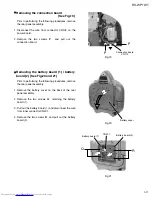
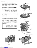
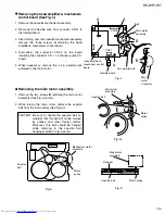
Removing the cassette mechanism
assembly (See Fig.3)
Fig.1
Fig.2
Fig.3
A
A
A
A
A
A
Connection board
CN112
Rear panel
assembly
B
B
B
CN624
CN614
CD mechanism
assembly section
Cassette mechanism assembly
CN33
CN34
C
C
C
Cassette mechanism
assembly
Wire cover
Summary of Contents for RS-WP1WT
Page 37: ...RS WP1WT 3 2 M E M O ...
Page 57: ...RS WP1WT 2 4 ...
Page 66: ...RS WP1WT 2 13 Tuner Board Block No 04 ...
Page 68: ...RS WP1WT 2 15 ...

