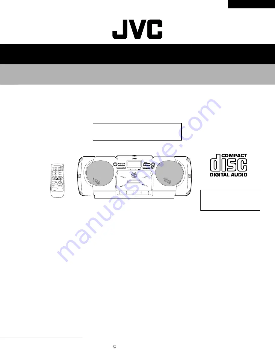
background image

SERVICE MANUAL

CD PORTABLE SYSTEM

No.20826C

Jan. 2001

COPYRIGHT       2001 VICTOR COMPANY OF JAPAN, LTD.

RV-B550BU

RV-B550BU

Area Suffix

Contents

Safety precautions ...................................1-2
Importance administering 
                      point on the safety ............. 1-3 
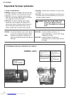
Important for laser products .................... 1-4
Preventing static electricity ...................... 1-5
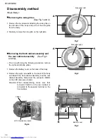
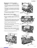
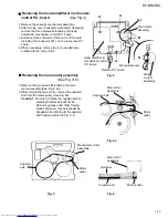
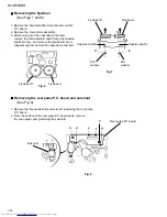
Disassembly method ............................... 1-6

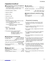
Adjustment method ................................. 1-15
Flow of functional operation 
                        until TOC read ................. 1-19
Maintenance of laser pickup .................... 1-20
Replacement of laser pickup ....................1-20
Description of major ICs .......................... 1-21~29

 UY ................ Argentina

This service manual adds UY version to the service manual
(RV-B550BU No.20826) previously issued.

This service manual is made from 100% recycled paper.

SLEEP

CLOCK

TIMER

  TIMER
 ON/OFF

PROGRAM

RANDOM

REPEAT

AUTO

PRESET

DISPLAY

REVERSE MODE

MULTI   CONTROL

REW

FF

 RM-RXVB55

REMOTE  CONTROL

TAPE

TUNER

 BAND

 FM MODE

C D

DOWN

UP

SET

AUX

VOLUME

AHB PRO

SOUND

ACS

Supplement

Summary of Contents for RV-B550BU

Page 1: ...5 Flow of functional operation until TOC read 1 19 Maintenance of laser pickup 1 20 Replacement of laser pickup 1 20 Description of major ICs 1 21 29 UY Argentina This service manual adds UY version to the service manual RV B550BU No 20826 previously issued This service manual is made from 100 recycled paper SLEEP CLOCK TIMER TIMER ON OFF PROGRAM RANDOM REPEAT AUTO PRESET DISPLAY REVERSE MODE MULT...

Page 2: ...current check Electrical shock hazard testing After re assembling the product always perform an isolation check on the exposed metal parts of the product antenna terminals knobs metal cabinet screw heads headphone jack control shafts etc to be sure the product is safe to operate without danger of electrical shock Do not use a line isolation transformer during this check Plug the AC line cord direc...

Page 3: ...1 1 0 A 250 V F1902 6 3 A 125 V F1903 6 3 A 125 V F1904 6 3 A 125 V F1901 1 0 A 250 V F1902 6 3 A 125 V F1903 6 3 A 125 V F1904 6 3 A 125 V RV B550J SEULEMENT Marquage Pour Le Remplacement Complet De Fusible PRECAUTIONS SUR LES FUSIBLES POUR UNE PROTECTION CONTINUE CONTRE DES RISQUES D INCENDIE REMPLACER SEULEMENT PAR UN FUSIBLE DU MEME TYPE Le symbole graphique Ce symbole signifie fusible de type...

Page 4: ...lning är denna del är öppnad och spårren är urkopplad Betrakta ej strålen VARO Avattaessa ja suojalukitus ohitettaessa olet alttiina näkymättömälle lasersäteilylle Älä katso säteeseen ADVARSEL Usynlig laserstråling ved åbning når sikkerhedsafbrydere er ude af funktion Undgå udsættelse for stråling ADVARSEL Usynlig laserstråling ved åpning når sikkerhetsbryteren er avslott unngå utsettelse for strå...

Page 5: ... destroy the laser diode 4 Handling the traverse unit optical pickup 1 Do not subject the traverse unit optical pickup to strong shocks as it is a sensitive complex unit 2 Cut off the shorted part of the flexible cable using nippers etc after replacing the optical pickup For specific details refer to the replacement procedure in the text Remove the anti static pin when replacing the traverse unit ...

Page 6: ...de grilles See Fig 1 and 2 Prior to performing the following procedure remove the right and left side grilles Remove the battery cover on the back of the body Remove the eight screws B on the back of the body and detach the front cabinet assembly and the rear cabinet assembly Disconnect the connector CN904 on the LED Illumination board 1 2 Removing the front cabinet assembly and the rear cabinet a...

Page 7: ...unit assembly toward the front 1 2 3 4 5 Removing the CD unit assembly See Fig 6 to 8 Prior to performing the following procedure remove the right and left side grilles and the front cabinet assembly Disconnect the card wires from connector CN405 and CN406 on the microcomputer board located on the underside of the CD unit of the rear cabinet assembly Remove the four screws C attaching head shield ...

Page 8: ...e amplifier board Disconnect the harness from connector CN192 and CN193 on the power supply board respectively Remove the two screws I attaching the power supply board Pull out the battery board 1 2 3 4 5 Remove the amplifier board the power supply board and the battery board See Fig 11 Prior to performing the following procedure remove the right and left side grilles the front cabinet assembly Di...

Page 9: ...ard Release the four tabs a fixing the right and left function buttons and the three tabs b by the key switch board Push tabs a and b in the directions of the arrows carefully not to damage the function buttons Remove the six screws K attaching the key switch board Pull out the key switch board from two tabs c 1 2 3 Removing the key switch board See Fig 14 and 15 CD unit assembly Fig 15 Fig 14 Fig...

Page 10: ...the CD cushion and the CD mechanism assembly respectively 1 2 Removing the CD mechanism assembly See Fig 16 Prior to performing the following procedure remove the CD mechanism assembly Remove the four screws M attaching the pickup cover Push the shaft stopper by the turn table in the direction of the arrow and pull out the shaft The pickup assembly comes off 1 2 Removing the pickup assembly See Fi...

Page 11: ...aching the speaker terminal 1 2 Removing the speakers See Fig 20 Front Cabinet Assembly Prior to performing the following procedure remove the front cabinet assembly and the rear cabinet assembly Remove the two screws N and two screws O attaching the LED boards on the speaker Disconnect the harness from connector FW251 and FW261 1 2 Removing the LED boards See Fig 20 Fig 20 P P P Q Speaker termina...

Page 12: ...g eraser head 7 Loosen the reversing azimuth screw retaining the playback recording eraser head 8 Take out the playback recording eraser head from the front of the head mount 9 The playback recoring eraser head should also be removed similarly according to Steps 1 8 above Reassembling the playback recording eraser head 1 Reassemble the playback head from the front of the head mount to the position...

Page 13: ...ews B retaining the main motor assembly See Fig 4 4a 2 While raising the main motor remove the capstan belt from the motor pulley See Fig 4a Caution 1 Be sure to handle the capstan belt so carefully that this belt will not be stained by grease and other foreign matter Moreover this belt should be hanged while referring to the capstan belt hanging method in Fig 5 6 Fig 4a Main motor assembly Capsta...

Page 14: ... flywheel R and L respectively from behind the cassette mechanism Removing the reel pulse P C board and solenoid See Fig 9 1 Remove the five pawls d h and screw C reataining the reel pulse P C board 2 From the surface of the reel pulse P C board parts remove the two pawls i and j retaining the solenoid Flywheel R Flywheel L Capstan shaft R Capstan shaft L Slit washer Slit washer Fig 8 i h d e f C ...

Page 15: ... 22 5 kHz Tuner section Voltage input to the tuner B DC 5 7 V VT DC 12 V Standard measuring output 26 1 mV 0 28 V 3ohm Input locations AM standard loop antenna FM TP1 hot and TP2 GND Standard settings for measuring volume Sound OFF Effective hyper bass OFF Volume adjustment VOL 23 Precautions for measuring 1 Input 30 pF and 33 kohm to the IF sweeper output and 0 082 F and 100 kohm to the sweeper i...

Page 16: ... the tape Head azimuth adjusting screw fast forward Head azimuth adjusting screw rewind Head azimuth adjusting screw fast forward Head azimuth adjusting screw rewind Head for recording playing and erasing the tape VR37 Motor speed TP Bias oscillation frequency wide pattern L301 Bias oscillation frequency VR31 Lch recording frequency bias adjustment VR32 Rch recording frequency bias adjustment ...

Page 17: ...ck the beginning of the VT 712 test tape 3 kHz in both directions Less than 60 Hz Should be confirmed when changing the motor Wow and flutter Test tape VT 712 3 kHz Measuring output terminal Headphone terminal Wow and flutter should be recorded at less than 0 25 WRMS when playing back the VT 712 test tape 3 kHz in the fast forward direction Less than 0 25 WRMS Electronic performance Items Conditio...

Page 18: ... AC 514 Measuring input terminal OSC IN Load the test tape AC 514 for TYPE II AC 225 for TYPE I into the tape playback mechanism and preset it to the record pause mode Input the standard value of 20 dB and the standard frequencies of 1 kHz and 10 kHz repeatedly to the microphone input from the transmitter in the recording mode Adjust VR31 for Lch and VR32 for Rch so that the difference in level be...

Page 19: ...asurement of TE amplitude and automatic tuning of TE balance 500mv div 2ms div Fig 1 Approx 3sec pin 25 of IC601 TE Approx 1 8V VREF Tracking error waveform at TOC reading Power ON Power Key Confirm that the Focus error S cuve siganl at the pin27 of IC601 is approx 2Vp p Confirm that the siganl from pin24 IC603 is 0V as a accelerated pulse during approx 400ms Confirm the waveform of the Tracking e...

Page 20: ...n the life of the laser diode has expired the following symptoms wil appear 1 The level of RF output EFM output ampli tude of eye pattern will below Is RF output 1 1 0 15Vp p Replace it NO YES O K 3 Semi fixed resistor on the APC PC board The semi fixed resistor on the APC printed circuit board which is attached to the pickup is used to adjust the laser power Since this adjustment should be perfor...

Page 21: ... FBAL EF EF OUT TE TE OUT CROSS TE BPF VDET LD OFF VREF ENV 30 24 25 26 23 22 1 4 3 33 32 34 31 36 35 13 14 15 16 20 2 21 6 29 7 28 27 8 9 10 17 11 12 19 ENV CURCUIT RF DET AGC EQ BDO OFTR VCBA VCBA VCBA VCBA 1 Terminal Layout 1 2 3 4 5 6 7 8 9 10 11 12 13 14 15 16 17 18 36 35 34 33 32 31 30 29 28 27 26 25 24 23 22 21 20 19 2 Block Diagram Description of major ICs ...

Page 22: ...verse input pin for tracking error amp Tracking error signal output Tracking error cross output Input pin of tracking error through BPF Vibration detection signal output Connect to ground Reference voltage output Functions and operations APC amp input terminal APC amp output terminal APC ON OFF control terminal Envelope output Ground RF detection signal output Of track status signal output BDO out...

Page 23: ... 9 10 11 12 13 14 15 16 17 2 5 4 7 18 1 3 RIPPLE FILTER BIAS CIRCUIT STANDBY SW IN IN POP NOISE PREVENTION CIRCUIT PREDRIVER PREDRIVER PREDRIVER PREDRIVER POWER POWER POWER POWER LOAD SHORT PROTECTOR LOAD SHORT PROTECTOR THERMEL SHUTDOWN OVER VOLTAGE SURGE PROTECTOR OUTPUT PIN TO Vcc SHORT PROTECTOR OUTPUT PIN TO Vcc SHORT PROTECTOR OUTPUT PIN TO GND SHORT PROTECTOR OUTPUT PIN TO GND SHORT PROTECT...

Page 24: ...rminal for volume control Terminal for 2ch volume output Terminal for connection of 2ch high frequency filter Terminal for connection of 2ch low frequency filter Terminal for gain adjustment of input step amp Terminal for 2ch volume output Terminal for filter I I O O I I I O I I Pin No Pin name Pin No Pin name I O Function Function I O 2 Pin function BH3852S IC501 E Volume 1 Block diagram FILTER I...

Page 25: ...Input output port Data input output Function IF counter signal input IF signal output Not use AM Local OSC signal output FM Local OSC signal input Power suplly VDD 4 5 5 5V When power ON Reset circuit move PLL charge pump output H Local OSC frequency Height than Reference frequency L Low Agreement Height impedance Input for active lowpassfilter of PLL Output for active lowpassfilter of PLL Connect...

Page 26: ...18 17 16 15 14 13 AM FM MONO SY VCC FM ANTENNA AM ANTENNA VT OSC Buff OUT IF OUT IF REQ AM RF IN FM RF OUT AM OSC FM OSC VCC1 OSC 0UT IF OUT REQ DET OUT MPX IN LPF 1 LPF 2 VCO FM RF IN GND 1 MIX OUT AGC VCC2 FM IF AM IF GND 2 FM DET FM DET ST IIND L OUT R OUT BPF AM RF AM OSC FM OSC Buff Buff AM REQ SW IF Buff AF Buff AM FM ST MONO SW 1 8 DIV AM DET FM MPX MUTE ST LED LEVEL DET AM IF FM IF AGC AM ...

Page 27: ...SUBQ AVDD2 CLVS CRC BLKCK CLDCK SBCK SUBC DEMPH RESY FLAG6 RESY EFM DEMODULATION SUBCODE DEMODULATION SYNC INTERPOLATION 16k SRAM CIRC ERROR CORRECTION DEINTERLEVE LRCKIN MSEL BCLK SSEL SRDATAIN PSEL IOSEL DIGITAL DEEMPHSIS 8TIMES OVER SAMPUNC DIGITAL FILTER 1BIT DAC LOGIC S PEM R PEM L DIGITAL AUDIO INTERFASE DIGITAL AUDIO INTERFASE INTER POLATION SOFT MUTING DIGITAL ATTENUATION PEAK DETECTIVE AU...

Page 28: ... signal output Kick pulse output Tracking drive output Focus drive output Reference voltage input pin for D A output block TVD FOD FBA TBAL Focus Balance adjust signal output Tracking Balance adjust signal output Focus error signal input Analog input Tracking error signal input Analog input RF envelope signal input Analog input Vibration detect signal input H detect Off track signal input H off tr...

Page 29: ...RV B550BU 1 29 1 OUT1 2 IN1 3 IN1 4 8 7 6 5 VEE VCC OUT2 IN2 IN2 2 1 BA15218F XE IC401 751 OP AMP ...

Page 30: ...Printed in Japan 200101 V VICTOR COMPANY OF JAPAN LIMITED AUDIO DIVISION 10 1 1Chome Ohwatari machi Maebashi city 371 8543 Japan No 20826C RV B550BU ...

Reviews: