


RV-B550BU
1-9
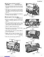
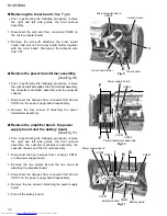
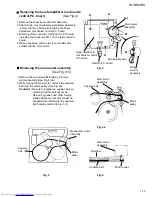
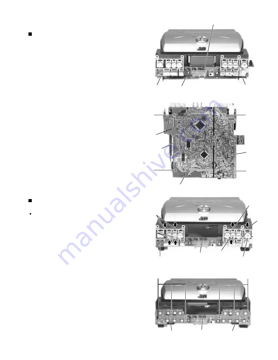
Disconnect the card wire from connector CN251 and
CN252 on the key switch board on the front side of
the CD unit assembly.
Remove the four screws J attaching the microcomputer
board on the underside of the CD unit assembly.
Disconnect the card wire or the harness from
connector CN601, CN602 and CN907 on the
microcomputer board respectively.
1.
2.
3.
Removing the microcomputer board
(See Fig.12 and 13)
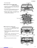
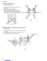
Prior to performing the following procedure, remove
the microcomputer board.
Release the four tabs a fixing the right and left
function buttons and the three tabs b by the key
switch board.
Push tabs a and b in the directions of the arrows
carefully not to damage the function buttons
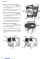
Remove the six screws K attaching the key switch
board.
Pull out the key switch board from two tabs c.
1.
2.
3.
Removing the key switch board
(See Fig.14 and 15)
<CD unit assembly>
Fig.15
Fig.14
Fig.12
Push
Push
CN252
CN251
Microcomputer board
Microcomputer board
J
J
J
J
CN602
CN601
CN907
Push
Push
Push
Push
Push
Push
Push
Push
a
b
a
b
Key switch board
Function switch buttons
(power)
Function switch buttons
(volume)
Key switch board
c
c
K
K
a
Key switch board
Push
Push
Push
Fig.13


