RX-5000VBK/RX-5001VGD
1-13
1
2
3
4
5
6
7
8
9
10
11
12
13
14
15
16
17
18
19
20
21
22
23
24
25~29
30
31
32
33~43
44
45.46
47
48~53
54
55
56
57
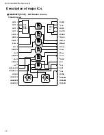
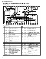
ECKO
ECKI
A.GND
A.GND
LchOUT
V-REF1
A.5V
A.5V
V-REF2
RchOUT
A.GND
A.GND
N.C
CchOUT
V-REF3
A.5V
VRO
VRI
A.5V
V-REF4
SchOUT
NC
A.GND
D.GND
NC
D.5V
D.5V
D.GND
NC
D.GND
NC
D.5V
NC
RESET
Non connect
Amplifier input terminal for external clock input.
Ground terminal.(For crystal oscillator circuit)
Ground terminal.(For DAC L channel)
DAC analog signal output terminal.(L channel)
Reference voltage terminal.(For DAC L channel)
Power supply terminal.(For DAC L channel)
Power supply terminal.(For DAC R channel)
Reference voltage terminal.(For DAC R channel)
DAC analog signal output terminal.(R channel)
Ground terminal.(For DAC R channel)
Ground terminal.(For DAC C channel)
DAC analog signal output terminal.(C channel)
DAC analog signal output terminal with attenuator.(For C channel)
Reference voltage terminal.(For DAC C channel)
Power supply terminal.(For DAC C channel)
Reference voltage terminal for attenuator.(Output buffer)
Reference voltage terminal for attenuator.(Input buffer)
Power supply terminal.(For DAC S channel)
Reference voltage terminal.(For DAC S channel)
DAC analog signal output terminal with attenuator.(For S channel)
Non connect.
Ground terminal.(For DAC S channel)
Ground terminal.
Non connect.
Power supply terminal.
Power supply terminal.(For DLRAM)
Ground terminal.(For DLRAM)
Non connect.
Ground terminal.
Non connect.
Power supply terminal.
Non connect.
Ground terminal.
Power supply.
Ground terminal.
Power supply.
-
I
-
-
O
-
-
-
-
O
-
-
O
O
-
-
O
I
-
-
O
-
-
-
-
-
-
-
-
-
-
-
-
-
-
-
I
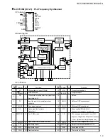
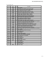
Pin No.
Symbol
I/O
Function
2.Pin Function (1/2)

