RX-5000VBK/RX-5001VGD
1-14
58
59~71
72
73
74
75
76
77
78
79
80
81,82
83
84~87
88
89
90
91
92,93
94
95
96,97
98
99
100
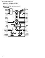
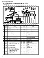
D.5V
DSP-CS
DSP-CLK
DATA-IN
DATA-OUT
DSP-IFOK
DSP-ACK
DSP-ERR
I2CS
BOOT
D.5V
D.GND
A.GND
LchIN
V-REF5
A.5V
V-REF6
RchIN
A.GND
XI
XO
A.5V
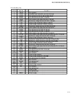
Pin No.
Symbol
I/O
Function
Power supply terminal
Non connect.
Chip select signal input terminal.(MCU interface)
Data sift clock input terminal.(MCU interface)
Data input terminal.(MCU interface)
At the IC bus mode,data input /output terminal.
Data output terminal.(MCU interface)
At the IC bus mode,normally open.
Operation flag output terminal.(MCU interface)
Acknowledge signal output terminal.(MCU interface)
Error flag output terminal.(MCU interface)
IC bus mode select terminal.
Self-boot control terminal.
Non connect.
Power supply terminal.
Ground terminal.
Digital ground terminal.(For ADC L channel)
Analog ground terminal.(For ADC L channel)
ADC analog signal input terminal.(L channel)
Reference voltage terminal.(For ADC L channel)
Analog power supply terminal.
Reference voltage terminal.(For ADC R channel)
ADC analog signal input terminal.(R channel)
Analog ground terminal.(For ADC R channel)
Crystal oscillator connection terminal.(input)
Crystal oscillator connection terminal.(output)
Power supply terminal.(For crystal oscillator circuit)
-
-
I
I
I/O
O
O
O
O
I
I
-
-
-
-
I
-
-
-
-
-
I
O
-
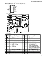
2.Pin Function (2/2)

