RX-8010RBK/ RX-8012RSL
1-23
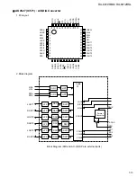
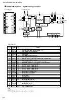
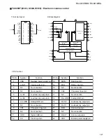
3.Block Diagram
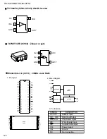
1.Terminal Layout
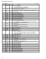
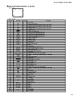
2.Pin Function
SAA6588 (IC191) : RDS detector
MRO
MPTH
TCON
OSCO
OSCI
VSSD
VDDD
DAVN
SDA
SCL
LVIN
CIN
SCOUT
Vref
MPX
VSSA
VDDA
AFW
MAD
PSWN
1
2
3
4
5
6
7
8
9
10
20
19
18
17
16
15
14
13
12
11
57 kHz
8th ORDER
BAND-PASS
CLOCK
COMPARATOR
RDS/RDBS
DEMODULATOR
RDS/RDBS
DECODER
PAUSE
DETECTOR
MULTI-PATH
DETECTOR
SIGNAL QUALITY
DETECTOR
INTERFACE
REGISTER
POWER
SUPPLY
AND RESET
TEST
CONTROL
OSCILLATOR
AND CLOCK
IC-BUS SLAVE
TRANSCEIVER
16
13
20
14
15
17
18
19
3
1
5
4
6
12
8
11
2
9
10
7
MPX
AFIN
LVIN
VDDA
VSSA
Vref
TCON
MRO
OSCI
OSCO
VSSD
MAD
SCL
SDA
MPTH
PSWN
DAVN
VDDD
CIN
SCOUT
MRO
MPTH
TCON
OSCO
OSCI
VSSD
VDDD
DAVN
SDA
SCL
PSWN
MAD
AFW
VDDA
VSSA
MPX
Vref
SCOUT
CIN
LVIN
1
2
3
4
5
6
7
8
9
10
11
12
13
14
15
16
17
18
19
20
Function
I/O
Symbol
Pin
No.
Multi-path rectifier output
Multi-path detector output
Test control input pin
Oscillator output
Oscillator input
Digital ground (0V)
Digital power supply (5V)
Data available output (active LOW)
IC-bus serial data I/O
IC-bus serial clock input
Pause switch output (active LOW)
Slave addrese (LSB) input
Audio signal input
Analog power supply (5V)
Connect to ground
Multiplex input signal
Reference voltage output
Band-pass filter output
Comparator output
Level input
O
-
I
O
I
-
-
O
I/O
I
-
-
-
-
-
I
O
O
O
I


