53
53
53
53
English
■
■
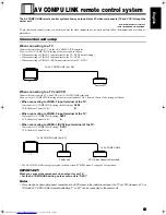
AV COMPU LINK remote control system
The AV COMPU LINK remote control system allows you to operate JVC video components (TV and VCR) through the
center unit.
To use this remote control system, you need to connect the video components you want to operate, follow the diagrams and procedure ex-
plained here.
Connection and setup
When connecting to a TV
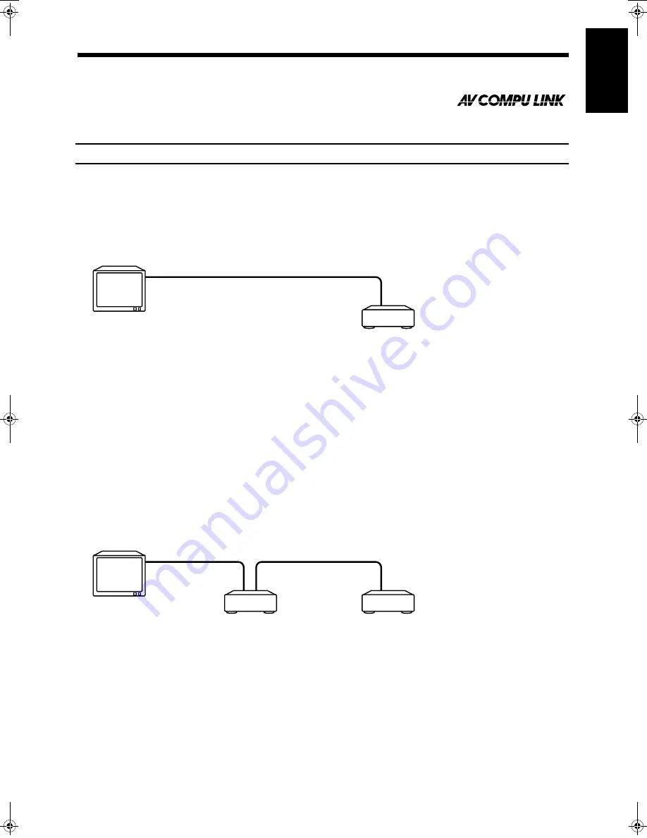
Connect the center unit to a TV via the AV COMPU LINK terminals.
Then, set the AV COMPULINK setting of the center unit as follows.
• When connecting to VIDEO-1 input terminal of the TV: DVD2 (Initial setting)
• When connecting to VIDEO-2 input terminal of the TV: DVD3
• When connecting to VIDEO-3 (DVD) input terminal of the TV: DVD1
When connecting to a TV and VCR
Connect the center unit to a TV and VCR via AV COMPU LINK terminals.
Then, set the AV COMPULINK setting of the center unit and the VCR’s Remote Control Code setting as follows:
• When connecting to VIDEO-1 input terminal of the TV:
• When connecting to VIDEO-2 input terminal of the TV:
• When connecting to VIDEO-3 (DVD) input terminal of the TV:
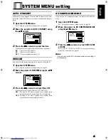
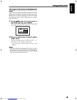
• The AV COMPULINK setting is operated in the on-screen SYSTEM menu. See page 45 for operation.
IMPORTANT!
When you connect the component video output to your TV:
• Set the AV COMPULINK setting on the center unit to “DVD1”.
Note:
• There may be no description about connections to a DVD player in the instruction manual of a TV or VCR. However a TV or
VCR with AV COMPU LINK terminals indicating “II” or “EX” can be connected to the center unit.
Center unit’s AV COMPULINK setting (Initial setting):
DVD2
VCR’s Remote Control Code:
B
Center unit’s AV COMPULINK setting:
DVD3
VCR’s Remote Control Code:
A
Center unit’s AV COMPULINK setting:
DVD1
VCR’s Remote Control Code:
A
To AV COMPU LINK (II or EX)
TV
Center unit
To AV COMPU LINK (II or EX)
To AV COMPU LINK
VCR (Video Cassette Recorder)
Center unit
TV
TH-A9(UW).book Page 53 Monday, March 12, 2001 9:17 AM


