(No.MB338)1-11
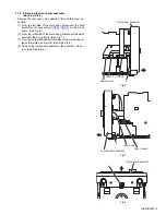
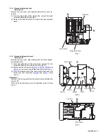
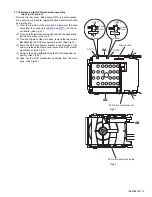
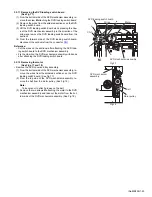
3.1.8 Removing the heat sink
(See Fig.11)
• Remove the rear cover, side panels(L)/(R) and top cover as-
sembly.
(1) From the back side of the main body, remove the eight
screws
N
attaching the heat sink.
(2) Remove the heat sink from the main board and regulator
board.
Fig.11
3.1.9 Removing the main board
(See Fig.12)
• Remove the rear cover, side panels(L)/(R), top cover assem-
bly and heat sink.
(1) From the right side of the main body, remove the two
screws
P
attaching the main board. (See Fig.12.)
(2) Disconnect the connectors (
CN101
to
CN104
,
CN106
and
CN110
) on the main board toward this side. (See Fig.12.)
(3) From the forward side of the main board, disconnect the
wires from the connectors (
CN109
and
CN111
). (See
Fig.12.)
Reference:
Remove it when a lug wire from the main board is installed with
a screw
Q
.
(When the screw
Q
and lug wire are installed, apply it.) (See
Fig.13.)
Fig.12
Fig.13
Heat sink
N
N
Regulator board
Main board
CN101
CN106
CN103
CN102
CN104
Main board
CN111
CN110
CN109
P
Main board
Lug wire
Q
Summary of Contents for SP-UXQD9S
Page 32: ...1 32 No MB338 SECTION 5 TROUBLESHOOTING This service manual does not describe TROUBLESHOOTING ...
Page 33: ... No MB338 1 33 ...
Page 41: ...2 5 SHEET 4 ...
Page 71: ...3 21 MEMO ...

