(No.MB338)1-15
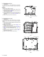
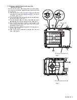
3.1.16 Removing the DVD mechanism assembly
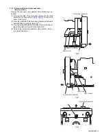
(See Figs.21 and 22)
• Remove the rear cover, side panels(L)/(R), top cover assem-
bly, heat sink, main board, regulator board, transformer board
and joint board.
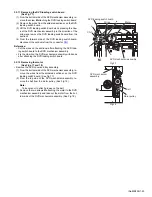
(1) From the top side of the main body, disconnect the card
wires from the connectors (
CN705
and
CN711
) on the mi-
con board. (See Fig.21.)
(2) From the left side of the main body, remove the spacers fix-
ing the card wires. (See Fig.21.)
(3) From the top side of the main body, remove the two screws
AA
attaching the DVD mechanism bracket. (See Fig.21.)
(4) Move the DVD mechanism bracket in the direction of the
arrow to release the claws
i
and remove the DVD mecha-
nism bracket. (See Fig.21.)
(5) Remove the screw
AB
attaching the DVD mechanism as-
sembly. (See Fig.22.)
(6) Take out the DVD mechanism assembly from the main
body. (See Fig.22.)
Fig.21
Fig.22
AA
AA
Micon board
CN705
i
i
DVD mechanism bracket
CN711
CN711
Spacer
Card
wire
CN705
Spacer
Card
wire
AB
DVD mechanism assembly
Summary of Contents for SP-UXQD9S
Page 32: ...1 32 No MB338 SECTION 5 TROUBLESHOOTING This service manual does not describe TROUBLESHOOTING ...
Page 33: ... No MB338 1 33 ...
Page 41: ...2 5 SHEET 4 ...
Page 71: ...3 21 MEMO ...

