1-22 (No.MB338)
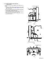
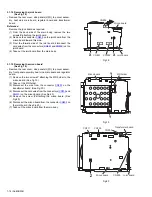
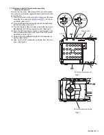
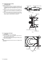
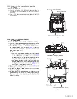
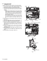
3.2.9 Removing the feed motor
(See Figs.13 to 15)
• Remove the DVD cover and traverse mechanism assembly.
(1) From the top side of the traverse mechanism assembly, re-
move the screw
H
attaching the plate and thrust spring.
(See Fig.13.)
(2) Remove the plate from the joint
n
of the feed holder and
take out the plate with the thrust spring. (See Fig.13.)
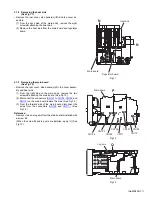
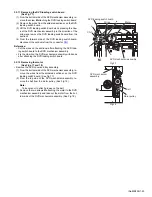
(3) Remove the wires from the soldered sections
p
on the spin-
dle motor board. (See Fig.14.)
Reference:
When attaching the feed motor, pass the wires through
the section
q
on the spindle base. (See Fig.14.)
(4) Remove the three screws
J
attaching the feed holder. (See
Fig.14.)
(5) Remove the feed holder, feed motor, lead screw, feed gear
E and feed gear M simultaneously. (See Fig.14.)
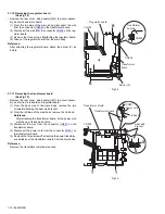
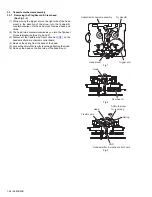
(6) From the side of the feed holder, remove the two screws
K
attaching the feed motor. (See Fig.15.)
3.2.10 Removing the spindle motor board
(See Fig.14 and 16)
• Remove the DVD cover, traverse mechanism assembly and
DVD module board.
(1) From the top side of the traverse mechanism assembly, re-
move the wires from the soldered sections
p
on the spindle
motor board. (See Fig.14.)
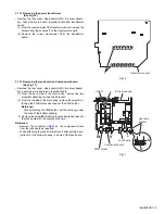
(2) From the bottom side of the traverse mechanism assem-
bly, remove the three screws
L
attaching the spindle motor
board. (See Fig.16.)
Fig.13
Fig.14
Fig.15
Fig.16
Thrust spring
Plate
H
n
Traverse mechanism assembly
Spindle motor board
Spindle base
Feed holder
Feed gear E
Feed gear M
Feed motor
Lead screw
Wires
q
J
J
p
Traverse mechanism assembly
Feed holder
K
Traverse mechanism assembly
L
Summary of Contents for SP-UXQD9S
Page 32: ...1 32 No MB338 SECTION 5 TROUBLESHOOTING This service manual does not describe TROUBLESHOOTING ...
Page 33: ... No MB338 1 33 ...
Page 41: ...2 5 SHEET 4 ...
Page 71: ...3 21 MEMO ...


