background image

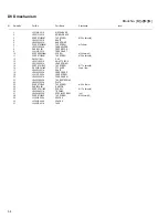
3-5

 73

QYSBSG3008ZA

TAP SCREW

M3 x 8mm

 74

VYSH101-009

SPACER

(x2)

 75

LV30225-079A

SPACER

 76

LV34035-001A

SHIELD

 77

LV30225-0J1A

SPACER

 78

LV30225-0M5A

SPACER

 79

QYSBSF3010ZA

TAP SCREW

M3 x 10mm(x4)

 80

E65923-009

TAPPING SCREW

 81

GV40034-001A

DAMPER ASSY.

 82

GV40220-001A

LACH

 83

LV43579-001A

DOOR SPRING

 84

QAU0346-001

TUNER

TU   1

 85

LV35102-001A

TUNER BKT

 86

QYSBSG3008ZA

TAP SCREW

M3 x 8mm(x2)

 87

QYSBSF3010ZA

TAP SCREW

M3 x 10mm

 88

QAR0312-001

FAN MOTOR

 89

QYSBSF3025ZA

TAP SCREW

M3 x 25mm

 90

LV30226-039A

SPACER

 91

LV44068-001A

BARRIER(A)

 92

VYSH101-009

SPACER

 93

QYSBSG3008ZA

TAP SCREW

M3 x 8mm

 94

LV44069-001A

BARRIER(B)

 95

VYSH101-009

SPACER

 96

LV44070-001A

BARRIER(C)

 97

QYSBSG3010ZA

TAP SCREW

M3 x 10mm(x2)

 98

QYSBSG3008ZA

TAP SCREW

M3 x 8mm

 99

LV30225-011A

SPACER

(x2)

100

LV10938-001A

SIDE PANEL(L)

101

LV10939-001A

SIDE PANEL(R)

102

QYSSST3008ZA

TAP SCREW

M3 x 8mm(x2)

103

LV10937-007A

REAR COVER

104

LV35067-001A

EARTH PLATE

105

QYSDSG3010NA

TAP SCREW

M3 x 10mm(x11)

106

QYSSST3008ZA

TAP SCREW

M3 x 8mm(x3)

107

GV40526-001A

CAUTION LABEL

108

LV44071-004A

REGION LABEL

A

108

LV44071-003A

REGION LABEL

UN,US

109

LV35063-004A

TRAY FITTING

110

GV30443-001A

VOLUME KNOB

111

LV35431-002A

RATING LABEL

A

111

LV35431-001A

RATING LABEL

UN

111

LV35431-003A

RATING LABEL

US

112

LV43614-001A

LABEL

113

QUQ410-0508DJ

FFC WIRE

5pin 8cm

114

QUQ110-1910AJ

FFC WIRE

19pin 10cm

115

QUQ410-0710DJ

FFC WIRE

7pin 10cm

116

QUQ110-1710BJ

FFC WIRE

17pin 10cm

117

QUQH10-0914AC

FFC WIRE

9pin 14cm

118

QUQ410-1518CJ

FFC WIRE

15pin 18cm

119

QUQ412-0920CJ

FFC WIRE

9pin 20cm

120

QUQ412-1020DJ

FFC WIRE

10pin 20cm

121

QUQ412-1124CJ

FFC WIRE

11pin 24cm

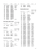
Symbol No.

Part No.

Part Name

Description

Local

Summary of Contents for SP-UXQD9S

Page 1: ... MB338 2004 12 MICRO COMPONENT SYSTEM MB338 2004 12 UX QD9S TABLE OF CONTENTS 1 PRECAUTION 1 3 2 SPECIFIC SERVICE INSTRUCTIONS 1 6 3 DISASSEMBLY 1 7 4 ADJUSTMENT 1 28 5 TROUBLESHOOTING 1 32 CA UXQD9S SP UXQD9S SP UXQD9S Area suffix A Australia US Singapore UN Asean ...

Page 2: ...Hz 9 kHz spacing 530 kHz 1 710 kHz 10 kHz spacing DVD player Playable discs DVD VIDEO DVD AUDIO CD VCD SVCD CD R CDRW CD VCD SVCD MP3 WMA JPEG format DVD R DVD RW video format Cassette deck Frequency response Normal type I 60 Hz 14 000 Hz Wow and flutter 0 15 WRMS General Power requirement AC 240 V 50 60 Hz UN US only AC 240 V 50 Hz A only Power consumption 70 W at operation 1 3 W on standby Dimen...

Page 3: ...ack control shafts etc to be sure the product is safe to operate without danger of electrical shock Do not use a line isolation transformer during this check Plug the AC line cord directly into the AC outlet Using a Leakage Current Tester measure the leakage current from each exposed metal parts of the cabinet particular ly any exposed metal part having a return path to the chassis to a known good...

Page 4: ...laser diode in the optical pickup The tester s internal power source can easily destroy the laser diode 1 6 Handling the traverse unit optical pickup 1 Do not subject the traverse unit optical pickup to strong shocks as it is a sensitive complex unit 2 Cut off the shorted part of the flexible cable using nippers etc after replacing the optical pickup For specific details refer to the replacement p...

Page 5: ...lock failed or defeated AVOID DIRECT EXPOSURE TO BEAM e VARNING Synlig och osynling laserstrålning när den öppnas och spärren är urkopplad Betrakta ej strålen s VARO Avattaessajasuojalukitus ohitettuna tai viallisena olet alttiina näkyvälle ja näkymättömälle lasersäteilylle Vältä säteen kohdistumista suoraan itseesi f ADVARSEL Synlig og usynlig laserstråling når maskinen er åben eller interlocken ...

Page 6: ...1 6 No MB338 SECTION 2 SPECIFIC SERVICE INSTRUCTIONS This service manual does not describe SPECIFIC SERVICE INSTRUCTIONS ...

Page 7: ...s 1 and 2 1 From the back side of the main body remove the eleven screws A attaching the rear cover See Fig 1 2 From the bottom side of the main body remove the three screws B attaching the rear cover See Fig 2 3 Remove the rear cover from the main body Fig 1 Fig 2 Rear cover A A A A Rear cover B ...

Page 8: ... Remove the screw D attaching the top cover assembly See Fig 4 3 From the right side of the main body disconnect the card wire from the connector CN105 on the main board See Fig 5 4 Disconnect the wire from the connector CN108 on the main board See Fig 5 Reference When connecting the wire pass it through the slot b of the main board as before See Fig 5 5 From the both sides of the main body remove...

Page 9: ...icon board See Fig 6 2 From the right side of the main body disconnect the earth wire from the micon board See Fig 7 3 From the both sides and bottom sides of the main body re lease the joints c and joint d See Figs 6 to 8 4 Remove the front panel assembly in the direction of the ar row See Figs 6 to 8 Fig 6 Fig 7 Fig 8 Micon board CN710 CN702 Front panel assembly c Front panel assembly Micon boar...

Page 10: ...From the inside of the top cover assembly remove the screw J attaching the tuner bracket See Fig 10 3 Take out the tuner with the tuner bracket 4 Remove the tuner from the tuner bracket 3 1 7 Removing the cassette mechanism assembly See Fig 10 Remove the rear cover side panels L R and top cover as sembly 1 From the inside of the top cover assembly remove the screw K screw L screws L and screw L at...

Page 11: ...m the right side of the main body remove the two screws P attaching the main board See Fig 12 2 Disconnect the connectors CN101 to CN104 CN106 and CN110 on the main board toward this side See Fig 12 3 From the forward side of the main board disconnect the wires from the connectors CN109 and CN111 See Fig 12 Reference Remove it when a lug wire from the main board is installed with a screw Q When th...

Page 12: ...ver assem bly heat sink main board and regulator board 1 From the back side of the main body remove the two screws S attaching the heat sink bracket 2 From the left side of the main body remove the tie band Reference After attaching the transformer board fix the power cord with the new tie band as before 3 Disconnect the wire from the connector CN903 on the transformer board 4 Disconnect the power...

Page 13: ...From the back side of the main body remove the two screws U attaching the heat sink bracket 2 From the top side of the main body remove the screw V at taching the PWB holder and take out the PWB holder Reference When attaching the PWB holder put the section g under the hook of the bottom chassis 3 Remove the screw W attaching the jack board and take out the jack board with the component board Refe...

Page 14: ...emoving the micon board See Fig 19 Remove the rear cover side panels L R top cover assem bly front panel assembly heat sink main board and regulator board 1 Remove the two screws Y attaching the MD holder to the micon board See Fig 19 2 Take out the MD holder 3 Disconnect the wire from the connector CN903 on the transformer board See Fig 20 4 Disconnect the card wires from the connectors CN705 and...

Page 15: ...emove the spacers fix ing the card wires See Fig 21 3 From the top side of the main body remove the two screws AA attaching the DVD mechanism bracket See Fig 21 4 Move the DVD mechanism bracket in the direction of the arrow to release the claws i and remove the DVD mecha nism bracket See Fig 21 5 Remove the screw AB attaching the DVD mechanism as sembly See Fig 22 6 Take out the DVD mechanism asse...

Page 16: ...e rear cover side panels L R top cover assem bly and front panel assembly 1 From the inside of the front panel assembly remove the three screws AD attaching the FL board 2 Take out the FL board from the front panel assembly Note When attaching the FL board be careful not to damage the LCD panel 3 1 19 Removing the key board See Figs 24 and 25 Remove the rear cover side panels L R top cover assem b...

Page 17: ... the projections a of the DVD mechanism assembly 4 Slide the DVD cover in the direction of the arrow and re move it from the sections b 5 Release the lock of the connector CN4 on the LED board and disconnect the card wire Fig 1 3 2 2 Removing the joint board See Fig 2 Remove the DVD cover 1 From the inside of the DVD cover remove the screw B at taching the joint board 2 Remove the spacer attaching...

Page 18: ...embly from the projec tions c on the DVD mechanism assembly and take out the tray assembly in an upward direction See Fig 4 Fig 3 Fig 4 3 2 4 Removing the LED board See Fig 5 Remove the DVD cover and tray assembly 1 From the top side of the tray assembly remove the sec tions d which were fixed in bond 2 Remove the double stick tape attaching the LED board and take out the LED board Note When remov...

Page 19: ...e disconnecting the card wire from the connector CN101 on the DVD module board If the card wire is discon nected without attaching solder the pickup may be de stroyed by static electricity See Figs 7 and 8 When attaching the DVD module board be sure to re move solders from the short land section e after con necting the card wire to the connector CN101 on the DVD module board See Figs 7 and 8 3 Dis...

Page 20: ...ting the card wire to the connector on the pickup See Figs 7 and 9 3 Remove the screw F attaching the plate and thrust spring See Fig 9 4 Remove the plate from the joint i of the feed holder and take out the plate with the thrust spring See Fig 9 5 Remove the shaft of the pickup from the section j of the traverse mechanism assembly and remove it from the sec tion k while moving the shaft in the di...

Page 21: ...and set the both ends of the shaft of the pickup in the sections j k of the traverse mechanism assembly See Fig 10 3 Attach the plate and thrust spring See Fig 9 4 Remove the solders from the soldered sections e after at taching the card wire to the connector on the pickup See Figs 7 and 9 5 Turn the feed gear M in the direction of the arrow 1 to move the pickup fully in the direction of the arrow...

Page 22: ...older feed motor lead screw feed gear E and feed gear M simultaneously See Fig 14 6 From the side of the feed holder remove the two screws K attaching the feed motor See Fig 15 3 2 10 Removing the spindle motor board See Fig 14 and 16 Remove the DVD cover traverse mechanism assembly and DVD module board 1 From the top side of the traverse mechanism assembly re move the wires from the soldered sect...

Page 23: ...d ing switch board to the DVD mechanism assembly Fix the claw t on the DVD mechanism assembly with bonds after attaching the DVD loading switch board 3 2 12 Removing the motor See Figs 17 and 18 Remove the DVD cover and tray assembly 1 From the bottom side of the DVD mechanism assembly re move the wires from the soldered sections r on the DVD loading switch board See Fig 17 2 From the top side of ...

Page 24: ...ise as you turn the flywheel R counterclockwise See Fig 2 and 3 3 Disconnect the flexible wire from connector CN31 on the head amplifier mechanism control board 4 Remove the spring from the back of the head 5 Loosen the azimuth screw for reversing attaching the head 6 Remove the head on the front side of the head mount Fig 1 Fig 2 Fig 3 Cassette mechanism assembly Fly wheelR Trigger arm Head mount...

Page 25: ...l pulse board REFERENCE If necessary unsolder the 4 pin wire soldered to the main motor 3 3 3 Removing the main motor See Fig 4 7 1 Remove the two screws B 2 Half raise the motor and remove the capstan belt from the motor pulley ATTENTION Be careful to keep the capstan belt from grease When reas sembling refer to Fig 6 and 7 for attaching the capstan belt Fig 4 Fig 5 Fig 6 Fig 7 Head amplifier mec...

Page 26: ...rd Fig 8 Fig 9 3 3 5 Removing the reel pulse board and solenoid See Fig 10 Prior to performing the following procedure remove the head amplifier mechanism control board 1 Remove the screw C 2 Release the tab a b c d and e retaining the reel pulse board 3 Release the tab f and g attaching the solenoid on the reel pulse board 4 The reel pulse board and the solenoid come off Fig 10 Fly wheel R Fly wh...

Page 27: ...the left to disengage the gear If the gear can not be disengaged easily push up the boss Q slightly and raise the rear side of the head mounts slightly to return the direction lever to the reversing side 2 Tighten the azimuth screw for reversing 3 Reattach the spring from the back of the Play Record Clear head 4 Connect the flexible wire to connector CN31 on the head amplifier mechanism control bo...

Page 28: ...5 DVD IOP check 4 1 3 Adjustment and check method Press the F SKIP key on the main unit While pressing both the STOP key and DVD PLAY key on the main unit insert the AC power cord in an outlet LCD indication TEST 1 EEPROM initialization Confirm that a disc is not in a tray Area suffix Region code Refer to item 4 EEPROM initialization starts LCD indication TEST 00 Press the F SKIP key on the main u...

Page 29: ...into a standby mode LCD indication UPGRADE Take out the disc from the tray after opening the tray automatically Upgrade is complete 3 Upgrade of system microcomputer ROM correction This set can do upgrade of a microcomputer with a ROM correction disc LCD indication NO DISC Source DVD Press the POWER key on the main unit and put the main body into a standby mode Press the OPEN CLOSE key on the main...

Page 30: ...l CHECK Check mode of the front end 0 30 00 Version number of the system control UT XXX XXX Version number of the DVD unit Confirm a number by a working standard which was provided with by manufacturing technique department Confirm that the area suffix fits the region code 3 Version indication of a DVD unit is displayed by pressing the ON SCREEN key on the remote controller in the system controlle...

Page 31: ... 4 key on the remote controller LCD indication AABB 0000 DVD IOP check is complete AA CD laser power in production mA BB CD laser power of the present mA LCD indication CHECK Press the 5 key on the remote controller LCD indication AABB 0000 AA DVD laser power in production mA BB DVD laser power of the present mA Press the POWER key on the main unit and put the main body into a standby mode Pull th...

Page 32: ...1 32 No MB338 SECTION 5 TROUBLESHOOTING This service manual does not describe TROUBLESHOOTING ...

Page 33: ... No MB338 1 33 ...

Page 34: ... No MB338 AV MULTIMEDIA COMPANY AUDIO VIDEO SYSTEMS CATEGORY 10 1 1chome Ohwatari machi Maebashi city 371 8543 Japan Victor Company of Japan Limited VPT Printed in Japan ...

Page 35: ...andard schematic diagrams Printed circuit boards 2 1 2 2 2 10 to 13 CD ROM No SML200412 MICRO COMPONENT SYSTEM No MB338SCH 2004 12 COPYRIGHT 2004 Victor Company of Japan Limited CA UXQD9S SP UXQD9S SP UXQD9S Area suffix A Australia US Singapore UN Asean ...

Page 36: ...ponent parts appearing on the silk screen printed side parts side of the PWB diagrams the parts that are printed over with black such as the resistor diode and ICP or identified by the mark nearby are critical for safety ...

Page 37: ... RCDG LCDB RCDB CN705 S2UDT SCS CPURST FDVD POUTPAMP CN621 COMPLNK COMPOSITE SDC YOUT OPTOUT AUXL AUXR OPTICAL OUT J6203 AV COMPULINK2 J6204 S COMPOSITE VIDEO OUT J6202 AUX Jack section Main section IC311 FUNCTION VOL IC CN103 CN106 CN110 CN105 VOLCK VOLCE VOLDATA POUTPAMP TUL TUR TAPEL TAPER DVDL DVDR INL INR AUXL AUXR DOUT CBIP CRIP YIP CI YI CYOUT CBOUT CROUT COMPO YOUT SDC CH COMPLINK VSW FANO...

Page 38: ...S133 T2 130 R2506 10 50 C2801 130 R2502 UNF D2502 1SS133 T2 D2501 1SS133 T2 D2901 1SS133 T2 10K R2901 Q2802 2SD601A RS X CN201 QGB2510K2 09 1 2 3 4 5 6 7 8 9 CN202 QGA2501C1 11 1 2 3 4 5 6 7 8 9 10 11 WR201 1 2 3 4 5 B8103 NI B8104 NI B8102 0 B8105 0 TH241 NAD0038 471X R2402 10k R2401 39k Q2401 2SD601A RS X B8202 ONLY_UX QD9 SUBTRDC LVA10524 A3 US6V DG B9901 POUTRELAY BUS BUS QQT0253 003 QQT0451 0...

Page 39: ... T 18K R6902 10 50 C6901 CN108 QGA2501F1 02 2 1 CN104 QGB2510J1 09 1 2 3 4 5 6 7 8 9 R1399 ECAP NI R1398 ECAP NI 22 50 C6008 NI R6002 120 R6007 IC601 MM1623XF X 28 27 26 25 24 23 22 21 20 19 18 17 16 15 14 13 12 11 10 9 8 7 6 5 4 3 2 1 0 1 C6006 K6001 QQR0621 001Z 120 R6009 0 1 C6003 0 1 C6004 C6001 470 10 C6007 0 1 10K R6013 NI R6006 R6008 470 NI R6004 10K R6012 0 1 16 C6002 0 1 C6005 470 R6010 1...

Page 40: ...1 72 73 74 75 76 77 78 79 80 81 82 83 84 85 86 87 88 89 90 91 92 93 94 95 96 97 98 99 100 Vss NI D7504 2 2K R7050 NI D7351 47K R7458 47K R7457 47K R7456 47K R7455 220 R7602 Q7601 UN2214 X D7601 1SS133 T2 10K R7601 0 01 C7354 0 01 C7353 K7451 NI 10 25 C7352 470 R7454 47 R7452 47 R7451 NI C7456 NI C7454 NI C7453 NI C7046 NI C7047 0 01 C7052 NI C7355 NI C7356 NI C7357 NI C7034 NI C7026 47K R7305 10K ...

Page 41: ...2 5 SHEET 4 ...

Page 42: ... MGND DGND M5V 10k 0 015 16 47K 30K 150P 270P 27K 0 1 16 22k 560p 0 1 16 DGND 0 1 16 1k 1k 0 DGND DGND 1 6 3 0 1 16 NI UN2119 X 150 150 NI 150 150 NI NI NI NAX0550 001X 15p D3 3V P3 3V 0 DGND 18p 0 0 33k 0 10K NAD0025 103X 0 1 16 2 2K NI 0 1 16 0 1 16 0 1 16 DGND P3 3V NI 0 0 DGND DGND D3 3V S3 3V 220 4 NI 220 1K 1K 1 6 3 NI NI 0 0 0 47 NI 0 1 16 330 330 0 01 16 NI NI 0 1 NI NI NI NI NI NQR0502 00...

Page 43: ... 22 6 3 NI NQR0129 002X NQR0129 002X NQR0129 002X NI NI NI NI NI NQR0129 002X NI 10k 0 0 1 16 0 1 16 NQL044K 100X NI NI NQR0129 002X AK4384VT X NI 0 NI NI 220 6 3 MGND 1 10 220 DGND 0 1 16 S3 3V 220 220 NI NI NI NI NI 0 0 1 16 D3 3V 0 NI 10 NI NI NI NI NI NI NI DGND 0 1 16 47k DGND NI 100 0 1 NI NI NI DGND QGF1016F2 19W 33p QGF1016F2 08W QGF1016F2 17W NQR0022 005X NQR0251 004X NI 0 NQR0251 004X NI...

Page 44: ...4 D1 D5 D6 D2 CN2 CN3 CN1 S1 R1 UDZS7 5B X UDZS7 5B X QGF1006F2 07W NSTM515AS UDZS7 5B X UDZS7 5B X NSTM515AS QGF1006F1 07W QGF1037F2 07W QGF1016F3 05 QSW1074 001 0 TO CN705 SHEET 3 TO CN711 SHEET 3 LED DVD loading section ...

Page 45: ...1K QVP0008 203Z KTC3199 GL T KTA1271 OY T 100K MTZJ5 1B T QGF1205F1 09 220p MSI 5U2LWA 2 2K QGF1201F3 10 CD4094BC 10 330P HA12238F 4 7 10K 10K 15K 15K KRC107M T 0 01 12K 9 1K 100 27K 2 2K QGF1205F1 09 QGF1205F1 09 QVP0077 103Z 330P QQR1118 001 10 16V VKZ3174 00B 3 9K SG 105F3 9 1K 3 3K 270P 2SB562 C KRC107M T 0 01 22K 47 50V 150P 1 50V 47 50V 150P QAH0101 001 2SK2001 0 0068 27K 11K 470K 4 7K KRA11...

Page 46: ... C1303 R3211 R1301 Q1301 Q1101 D2301 R3155 R6901 D6901 D6902 Q6901 R6902 C6901 CN108 CN104 R1399 R1398 R6071 C6008 R6002 R6007 IC601 C6099 J1002 C6006 K6001 R6009 R6072 C6003 R6074 C6004 C6001 C6007 R6013 C6076 C6075 R6006 R6008 R6004 R6012 R6076 C6002 R6079 C6074 R6070 R6078 R6075 R6073 C6073 C6071 C6005 R6010 R6005 R6003 R6001 Q6902 C6902 CN106 R3366 C6093 R6094 C6072 CN110 R2803 R2804 D2803 B19...

Page 47: ...352 CN709 C7634 R7632 R7631 R7032 R7033 R7046 R7053 R7054 R7044 R7007 R7008 R7055 R7067 R7028 R7027 R7026 R7024 R7066 R7073 R7074 R7075 R7056 R7097 R7096 R7099 R7098 R7002 R7001 R7003 R7010 R7011 R7013 R7014 R7015 R7016 R7076 R7077 R7078 R7079 R7080 R7081 R7083 R7084 R7085 R7157 R7088 R7089 R7090 R7091 R7093 R7094 R7095 R7017 R7018 R7019 R7020 R7021 R7022 R7057 R7058 R7059 R7060 R7062 L7024 R7068 ...

Page 48: ...TP327 TP701 TP702 TP703 TP704 TP705 TP706 X351 TP328 CN201 IC201 TP330 R384 R385 C371 TP351 C553 R501 R502 K564 K565 K566 K567 R558 R382 R383 R510 R511 TP54 R704 TP332 TP333 R324 R325 R326 K302 C559 R378 R379 C715 C713 C712 C714 R719 R716 R717 R720 C508 C509 C510 C511 K501 C548 C549 C550 C547 C328 R344 C265 C266 C267 K252 C102 C105 C106 C108 C109 C110 C204 C217 C260 C261 C262 C263 C264 C301 C302 C...

Page 49: ...33 CN34 Q348 D375 IC32 IC33 L301 L303 Q302 Q305 Q342 Q343 Q344 Q345 Q346 Q371 Q372 Q375 Q376 R101 R102 R104 R105 R106 R107 R108 R110 R116 R121 R201 R202 R204 R205 R206 R207 R208 R210 R216 R221 R301 R302 R303 R304 R305 R306 R310 R313 R314 R315 R327 R335 R336 R337 R338 R339 R340 R341 R342 R343 R344 R345 R346 R353 R372 R375 R376 VR31 CN32 C214 C204 C104 C211 Q347 R347 W1 W1 PP300 C220 C120 C212 Casse...

Page 50: ...Victor Company of Japan Limited No MB338SCH Printed in Japan VPT AV MULTIMEDIA COMPANY AUDIO VIDEO SYSTEMS CATEGORY 10 1 1chome Ohwatari machi Maebashi city 371 8543 Japan ...

Page 51: ...embly and parts list Block No M2 DVD mechanism assembly and parts list Block No MJ DVD loading base assembly and parts list Block No MN Cassette mechanism assembly and parts list Block No MP Electrical parts list Block No 01 07 Packing materials and accessories parts list Block No M3 UX QD9S 3 2 3 6 3 7 3 9 3 11 3 13 3 22 Area suffix A Australia US Singapore UN Asean No MB338 ...

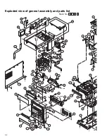
Page 52: ... G F B A L B d c b m e a a e H J J H w w 84 121 68 69 70 72 74 73 76 79 11 79 14 14 14 18 18 10 5 4 2 7 110 1 2 8 119 71 83 49 43 41 37 2 19 25 22 21 120 115 109 117 56 9 9 9 79 77 3 17 13 12 80 81 82 15 15 100 102 102 2 113 45 6 6 46 118 74 79 78 75 23 39 16 96 98 86 85 87 89 88 90 97 97 99 99 50 ...

Page 53: ... s a v J v u p w x x N N y y z z Jack board c Y Y Regulator board 51 49 43 41 40 37 61 66 62 44 63 64 65 64 64 65 28 29 31 61 38 36 36 20 19 21 55 35 117 114 32 60 42 31 61 111 54 43 101 67 26 106 106 106 105 105 105 105 105 105 103 48 55 20 33 34 52 53 116 47 24 30 32 27 45 57 46 118 104 58 107 23 39 59 105 91 94 95 93 99 99 50 51 92 112 108 ...

Page 54: ...mm x3 33 QZW0033 001 STRAIN RELIEF 34 QMPG080 244 JD POWER CORD EU 2 44m BLACK A 34 QMPK210 205 JN POWER CORD EU 2 05m BLACK UN US 35 LV35064 001A HEAT SINK BKT 36 QYSDST3006EA TAP SCREW M3 x 6mm x2 37 QYSBSF3012ZA TAP SCREW M3 x 12mm 38 LV30225 011A SPACER x2 39 LV42035 002A LASER CAUTION 40 LV21754 001A DVD MECHA BKT 41 LV30225 0Q7A SPACER 42 LV30225 0U5A SPACER 43 QYSDST3006EA TAP SCREW M3 x 6m...

Page 55: ... M3 x 8mm 99 LV30225 011A SPACER x2 100 LV10938 001A SIDE PANEL L 101 LV10939 001A SIDE PANEL R 102 QYSSST3008ZA TAP SCREW M3 x 8mm x2 103 LV10937 007A REAR COVER 104 LV35067 001A EARTH PLATE 105 QYSDSG3010NA TAP SCREW M3 x 10mm x11 106 QYSSST3008ZA TAP SCREW M3 x 8mm x3 107 GV40526 001A CAUTION LABEL 108 LV44071 004A REGION LABEL A 108 LV44071 003A REGION LABEL UN US 109 LV35063 004A TRAY FITTING...

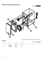
Page 56: ...aker Block No M 2 M M Symbol No Part No Part Name Description Local 1 LV21811 001A NET ASSY x2 2 5600008011 HOLDER x8 3 9000007941 FOOT x8 4 LV43473 002A JVC MARK x2 Block No M M M 2 The parts without symbol number are not service 4 1 3 3 2 ...

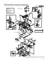
Page 57: ...6 12 13 14 15 Back side Back side 25 20 Grease 1401C PG 641 CFD 4007ZY2 JVG 31N 17 6 21 22 23 8 9 7 31 10 19 18 2 30 1 3 4 11 11 27 63 3mm DVD module board 0 1mm 10 5mm 0 1mm A A FTU JZ1 11M 27 27 5 26 27 28 24 29 The parts without symbol number are not service ...

Page 58: ...SCREW M2 6 x 5mm x3 12 QAL0577 001 P UP 13 LE20732 001A SW ACTUATOR 14 LE31093 001A LEAD SPRING 15 QYSPSFU1740Z TAP SCREW M1 7 x 4mm x2 16 QUQ105 2412AC FFC WIRE 24pin 12cm 17 LE40931 001A SHAFT 18 LE40855 002A FEED GEAR E 19 LV41517 003A LEAD SCREW 20 LE40930 001A FEED GEAR M 21 LE40928 002A THURUST SPRING 22 LE40927 002A PLATE 23 QYSDST2614Z TAP SCREW M2 6 x 14mm 24 QAR0334 001 S MOTOR 25 QYSPSP...

Page 59: ...75mm 0 10mm a b e h j j f e f c d c h d FMU JZ1 11M Switch board LED board Joint board Backside The parts without symbol number are not service 1 2 21 3 19 7 4 5 6 8 17 18 9 11 10 23 24 25 26 28 26 27 12 16 13 31 32 34 34 34 33 14 15 22 20 30 29 FL 7750E JVG 31N Grease ...

Page 60: ...T 14 QYSSSP2010ZA SCREW M2 x 10mm 15 QYNNS2000ZA NUT M2 16 QYSDSF2008Z TAP SCREW M2 x 8mm x2 17 QAR0197 001 MOTOR 18 LV43844 001A MOTOR PULLEY 19 QYSPSPU1730Z SCREW M1 7 x 3mm x2 20 QYSDSF2008Z TAP SCREW M2 x 8mm 21 LV43974 001A BELT 22 LV21747 001A CLAMPER BASE 23 LV43958 001A SPECIAL SCREW 24 LV30225 011A SPACER 25 QUQ710 0712AE FFC WIRE 7pin 12cm 26 QYSDSF2008Z TAP SCREW M2 x 8mm x2 27 LV35056 ...

Page 61: ... 27 13 3 34 2 8 15 10 14 16 7 12 23 3 2 4 9 6 5 24 29 25 22 17 20 19 18 11 21 31 36 26 28 30 1 11 6 5 33 32 33 32 35 35 SLC S302M A B 8 7 _ 0 1 0 15 mm A B C C Block No M M M P Grease The lower side Head amplifier board Switch board The parts without symbol number are not service ...

Page 62: ... 14 LV41584 001A BRAKE R 15 LV41585 003A BRAKE L 16 QYSBSF2005Z SCREW 2mm x 5mm 17 VKS5603 00G MAIN PULLEY ASS 18 VKS3785 001MM FR ARM 19 VKW5284 002 SWING SPRING 20 VKS2278 003 TRIGGER ARM 21 VKW5301 001 FR SPRING 22 VKW5266 001 ELEVATOR SPRING 23 WDL214025 WASHER 24 QYSBSF2005Z SCREW 2mm x 5mm 25 VKS3786 00G CLUTCH ASSY 26 VKF3205 00B F WHEEL ASSY R 27 WDL183425 SLIT WASHER 28 VKF3207 00C F WHEE...

Page 63: ...M C3109 QFG32AJ 272Z PP CAPACITOR 2700pF 100V J C3110 QFVF1HJ 104Z MF CAPACITOR 0 1uF 50V J C3111 QFVF1HJ 104Z MF CAPACITOR 0 1uF 50V J C3112 QFVF1HJ 184Z MF CAPACITOR 0 18uF 50V J C3113 QFVF1HJ 184Z MF CAPACITOR 0 18uF 50V J C3114 QFVF1HJ 823Z MF CAPACITOR 0 082uF 50V J C3115 QETN1HM 226Z E CAPACITOR 22uF 50V M C3116 QETN1HM 334Z E CAPACITOR 0 33uF 50V M C3117 QFVF1HJ 823Z MF CAPACITOR 0 082uF 50...

Page 64: ...SA63J 332X MG RESISTOR 3 3kΩ 1 16W J R5012 NRSA63J 272X MG RESISTOR 2 7kΩ 1 16W J R5013 NRSA63J 392X MG RESISTOR 3 9kΩ 1 16W J R5014 NRSA63J 682X MG RESISTOR 6 8kΩ 1 16W J R5015 NRSA63J 123X MG RESISTOR 12kΩ 1 16W J R5016 NRSA63J 393X MG RESISTOR 39kΩ 1 16W J R5021 NRSA63J 332X MG RESISTOR 3 3kΩ 1 16W J R5022 NRSA63J 272X MG RESISTOR 2 7kΩ 1 16W J R5023 NRSA63J 392X MG RESISTOR 3 9kΩ 1 16W J Symbo...

Page 65: ...01uF 50V K C2903 QETN1CM 107Z E CAPACITOR 100uF 16V M C6211 QETN1EM 476Z E CAPACITOR 47uF 25V M C6212 NCB31HK 103X C CAPACITOR 0 01uF 50V K C6215 NCB31HK 561X C CAPACITOR 560pF 50V K C6225 NCB31HK 561X C CAPACITOR 560pF 50V K C6230 NCB31HK 103X C CAPACITOR 0 01uF 50V K C6291 QETN0JM 477Z E CAPACITOR 470uF 6 3V M C6292 QETN0JM 477Z E CAPACITOR 470uF 6 3V M C6294 NDC31HJ 101X C CAPACITOR 100pF 50V J...

Page 66: ...MG RESISTOR 2 2kΩ 1 16W J R7081 NRSA63J 222X MG RESISTOR 2 2kΩ 1 16W J Symbol No Part No Part Name Description Local R7083 NRSA63J 222X MG RESISTOR 2 2kΩ 1 16W J R7084 NRSA63J 222X MG RESISTOR 2 2kΩ 1 16W J R7085 NRSA63J 222X MG RESISTOR 2 2kΩ 1 16W J R7086 NRSA63J 222X MG RESISTOR 2 2kΩ 1 16W J R7087 NRSA63J 223X MG RESISTOR 22kΩ 1 16W J R7088 NRSA63J 222X MG RESISTOR 2 2kΩ 1 16W J R7089 NRSA63J ...

Page 67: ...47uF 6 3V M C111 NCB31CK 104X C CAPACITOR 0 1uF 16V K C204 NCB31CK 104X C CAPACITOR 0 1uF 16V K C205 NCB31HK 271X C CAPACITOR 270pF 50V K C206 NDC31HJ 151X C CAPACITOR 150pF 50V J C208 NCB31HK 561X C CAPACITOR 560pF 50V K C211 NCB31HK 223X C CAPACITOR 0 022uF 50V K C212 NCB31CK 103X C CAPACITOR 0 01uF 16V K C217 NCB31CK 104X C CAPACITOR 0 1uF 16V K C251 NCB31AK 474X C CAPACITOR 0 47uF 10V K C253 N...

Page 68: ... R308 NRSA63J 223X MG RESISTOR 22kΩ 1 16W J R309 NRSA63J 104X MG RESISTOR 100kΩ 1 16W J Symbol No Part No Part Name Description Local R310 NRS125J R47X MG RESISTOR 0 47Ω 1 2W J R312 NRSA63J 0R0X MG RESISTOR 0Ω 1 16W J R313 NRSA63J 0R0X MG RESISTOR 0Ω 1 16W J R314 NRSA63J 0R0X MG RESISTOR 0Ω 1 16W J R315 NRSA63J 0R0X MG RESISTOR 0Ω 1 16W J R316 NRSA63J 0R0X MG RESISTOR 0Ω 1 16W J R317 NRSA63J 0R0X ...

Page 69: ...2SC2001 K T TRANSISTOR Q305 2SC2001 K T TRANSISTOR Q342 KRA111M T DIGI TRANSISTOR Q343 2SC3576 JVC T TRANSISTOR Q344 2SC3576 JVC T TRANSISTOR Q345 2SC3576 JVC T TRANSISTOR Q346 2SC3576 JVC T TRANSISTOR Q347 KRC107M T DIGI TRANSISTOR Q371 KTA1271 OY T TRANSISTOR Q372 KRC107M T DIGI TRANSISTOR Q375 2SB562 C T TRANSISTOR Q376 KTC3199 GL T TRANSISTOR D340 MTZJ5 1B T2 Z DIODE D375 MTZJ5 1B T2 Z DIODE C...

Page 70: ... J R310 QRJ146J 4R7X UNF C RESISTOR 4 7Ω 1 4W J R313 QRE141J 2R2Y C RESISTOR 2 2Ω 1 4W J R314 QRE141J 153Y C RESISTOR 15kΩ 1 4W J R315 QRE141J 101Y C RESISTOR 100Ω 1 4W J R327 QRE141J 474Y C RESISTOR 470kΩ 1 4W J R335 QRE141J 222Y C RESISTOR 2 2kΩ 1 4W J R336 QRE141J 223Y C RESISTOR 22kΩ 1 4W J R337 QRE141J 332Y C RESISTOR 3 3kΩ 1 4W J R338 QRE141J 392Y C RESISTOR 3 9kΩ 1 4W J R339 QRE141J 104Y C ...

Page 71: ...3 21 MEMO ...

Page 72: ...nd accessories parts list Block No M M M 3 No additional supplemental order of WARRANTY CARDs are available P4 P3 P2 A2 P5 P3 P2 A3 1 2 1 2 2 2 2 2 A4 P1 P7 2 2 P9 P8 P11 P7 1 2 1 2 P8 2 2 P10 P11 P10 A9 A10 A1 A6 A7 A5 A8 P6 ...

Page 73: ... QAL0014 001 AM LOOP ANT A 8 WARRANTY CARD BT 56012 1 A A 9 UXQD9SK SPBOX L SPEAKER BOX A 10 UXQD9SK SPBOX R SPEAKER BOX P 1 LV35434 001A CARTON A P 1 LV35434 002A PACKING CASE UN US P 2 LV21756 001A CUSHION BOTTOM P 3 LV21757 001A CUSHION TOP P 4 QPC05006515P POLY BAG 50cm x 65cm P 5 QPC02503510P POLY BAG 25cm x 35cm P 6 QPA01503503 POLY BAG 15cm x 35cm A P 7 LV35279 001A TOP CUSHION P 8 LV35279 ...

Reviews: