TH-V70
1-29
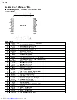
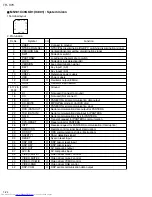
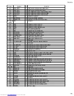
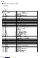
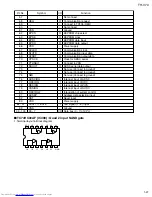
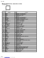
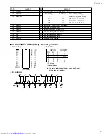
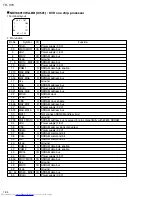
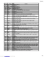
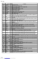
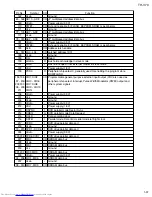
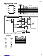
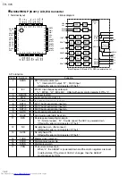
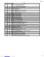
Pin No.
Symbol
I/O
TILT
TILTN
TX
DTRD
IDGT
VDD18
VSS
VDD3
OSCI1
OSCO1
VSS
TSTSG
VFOSHORT
JLINE
AVSS
ROUT
LOUT
AVDD
VCOF
TRCRS
CMPIN
LPFOUT
LPFIN
AVSS
HPFOUT
HPFIN
CSLFLT
RFOIF
AVDD
PLFLT2
PLFLT1
AVSS
RVI
VREFH
PLPG
VHALF
DSLF2
DSLF1
AVDD
NARF
ARF
JITOUT
AVSS
DAC0
DAC1
AVDD
AD0
AD1
AD2
-
-
-
-
-
-
-
-
I
-
-
O
O
O
-
-
-
-
I
I
-
-
I
-
-
I
I
-
-
I
I
-
I
I
-
I
I
I
-
I
I
O
-
O
O
-
I
I
I
Not connect
Not connect
Not connect
Not connect
Not connect
Power supply (1.8V)
Ground
Power supply (1.8V)
16.9MHz clock input
Not connect
Ground
Calibration signal
VFO short output
J-line setting output
Analog ground
Not connect
Not connect
Analog power supply
JFVCO control voltage
Input signal for track cross formation
Not connect
Not connect
Pull-up to VHALF
Analog ground
Not connect
HPF input
Pull-up to VHALF
Not connect
Analog power supply
Connect to capacitor 2 for PLL
Connect to capacitor 1 for PLL
Analog ground
Connect to resistor for VREF reference current source
Reference voltage input (2.2V)
Not connect
Reference voltage input (1.65V)
Connect to capacitor 2 for DSL
Connect to capacitor 1 for DSL
Analog power supply
Equivalence RF-
Equivalence RF+
Output for jitter signal monitor
Analog ground
Tracking drive output
Focus drive output
Analog power supply
Focus error input
Phase difference/3 beams tracking error
AS: Full adder signal
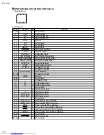
71
72
73
74
75
76
77
78
79
80
81
82
83
84
85
86
87
88
89
90
91
92
93
94
95
96
97
98
99
100
101
102
103
104
105
106
107
108
109
110
111
112
113
114
115
116
117
118
119
Function
Summary of Contents for TH-V70
Page 55: ...TH V70 1 55 M E M O ...

