


(No.MB674<Rev.003>)1-9
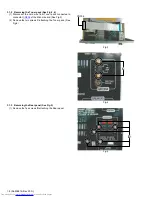
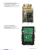
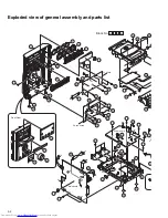
3.1.4 Removing the Amp board (See Fig.6)
(1) Disconnect the connector wire from Power board connect-
ed to connector
CN640
of the Amp board.
(2) Disconnect the card wire from Amp board connected to
connector
CN520
of the Micom board.
(3) Remove the one screw
E
attaching the Amp board.
Fig.6
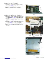
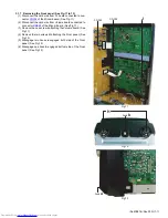
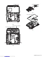
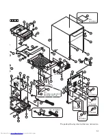
3.1.5 Removing the DVD mechanism (See Fig.7 to 8)
(1) Disconnect the card wire from DVD mechanism connected
to connector
CN360
and
CN361
of the Connection board.
(See Fig.7)
(2) Disconnect the connector wire from DVD mechanism con-
nected to connector
CN811
of the Connection board. (See
Fig.7)
(3) Disconnect the card wire from DVD mechanism connected
to connector
CN205
of the Power board. (See Fig.7)
(4) Disconnect the card wire from DVD mechanism connected
to connector
CN510
of the Micom board. (See Fig.7)
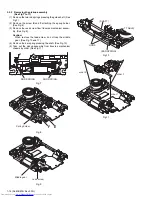
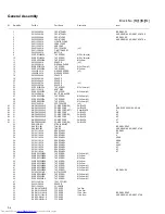
(5) Remove the two screws
F
attaching the DVD mechanism.
(See Fig.8)
Fig.7
Fig.8
E
CN640
CN520
CN205 CN361
CN360
CN811
CN510
F
Summary of Contents for UV-G500VA
Page 41: ...3 21 MEMO ...
Page 60: ... M E M O ...


