background image

1-12 (No.MB595)

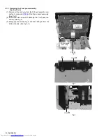
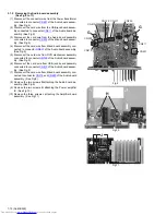
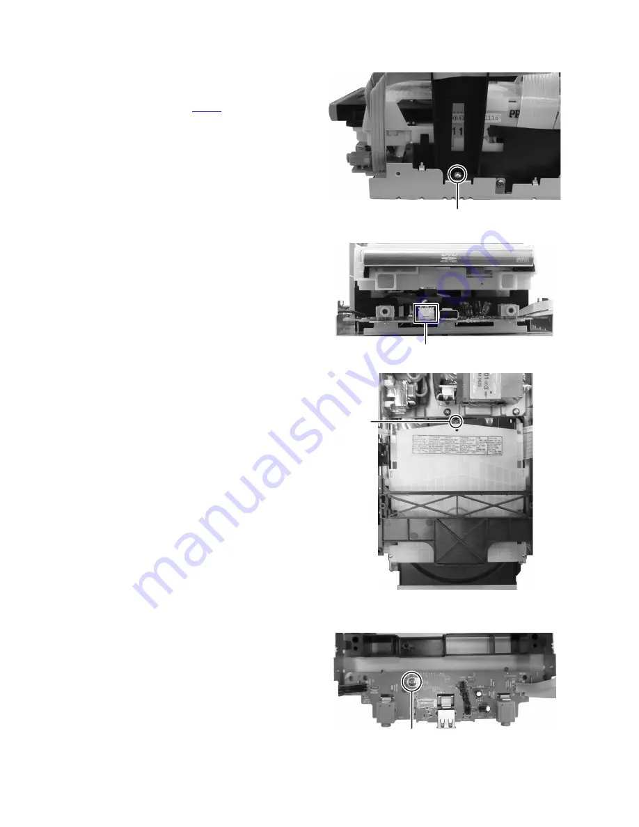
3.1.7 Removing the DVD mechanism assembly 

(See Fig.14 to 16)

(1) Remove the two screws 

M

 (both side) attaching the brack-

et. (See Fig.14)

(2) Disconnect the connector wire from DVD mechanism as-

sembly connected to connector 

CN803

 of the USB jack

board assembly. (See Fig.15)

(3) Remove the one screw 

N

 attaching the DVD mechanism

assembly. (See Fig.16)

Fig.14

Fig.15

Fig.16

3.1.8 Removing the USB jack board assembly 

(See Fig.17)

(1) Remove the one screw 

P

 attaching the USB jack board as-

sembly.

Fig.17

M

CN803

N

P

Summary of Contents for UX-G68E

Page 1: ...2007 Victor Company of Japan Limited Lead free solder used in the board material Sn Ag Cu melting point 219 Centigrade Lead free solder used in the board material Sn Cu melting point 230 Centigrade TABLE OF CONTENTS 1 PRECAUTION 1 3 2 SPECIFIC SERVICE INSTRUCTIONS 1 6 3 DISASSEMBLY 1 7 4 ADJUSTMENT 1 20 5 TROUBLESHOOTING 1 21 CA UXG68 SUPER VIDEO SP UXG68 SP UXG68 ...

Page 2: ...AT THE USER SWITCH THE CONNECTION TO THE STANDARD DEFINITION OUTPUT IF THERE ARE QUESTIONS REGARDING OUR TV SET COMPATIBILITY WITH THIS MODEL 525p AND 625p DVD PLAYER PLEASE CONTACT OUR CUSTOMER SER VICE CENTER Amplifier Output Power 120 W 60 W 60 W at 6Ω 10 THD Audio Input AUX 500 mV 50 kΩ at AUX LVL1 250 mV 50 kΩ at AUX LVL2 125 mV 50 kΩ at AUX LVL3 Digital output DVD OPTICAL DIGITAL OUT 21 dBm ...

Page 3: ...ack control shafts etc to be sure the product is safe to operate without danger of electrical shock Do not use a line isolation transformer during this check Plug the AC line cord directly into the AC outlet Using a Leakage Current Tester measure the leakage current from each exposed metal parts of the cabinet particular ly any exposed metal part having a return path to the chassis to a known good...

Page 4: ...condition of the laser diode in the optical pickup The tester s internal power source can easily destroy the laser diode 1 6 Handling the traverse unit optical pickup 1 Do not subject the traverse unit optical pickup to strong shocks as it is a sensitive complex unit 2 Cut off the shorted part of the flexible cable using nippers etc after replacing the optical pickup For specific details refer to ...

Page 5: ...t uses visible and or invisible laser radiation and is equipped with safety switches which prevent emission of radiation when the drawer is open and the safety interlocks have failed or are defeated It is dangerous to defeat the safety switches 5 CAUTION If safety switches malfunction the laser is able to function 6 CAUTION Use of controls adjustments or performance of procedures other than those ...

Page 6: ...1 6 No MB595 SECTION 2 SPECIFIC SERVICE INSTRUCTIONS This service manual does not describe SPECIFIC SERVICE INSTRUCTIONS ...

Page 7: ...emoving the Metal cover See Fig 1 and 2 1 Remove the four screws A both side attaching the Metal cover See Fig 1 2 Remove the two screws B attaching the Rear cover See Fig 2 3 Remove the five screws C attaching the Metal cover See Fig 2 Fig 1 Fig 2 A B C C C ...

Page 8: ...d assembly con nected to connector CN205 of the Micon board assembly See Fig 3 2 Remove the two screws D attaching the Front panel as sembly See Fig 4 3 Disengage the hook a Fig 4 and hook b Fig 5 from the bottom chassis See Fig 4 5 Fig 3 Fig 4 Fig 5 CN205 FL board assembly Micon board assembly Hook a D D Hook b ...

Page 9: ...board assembly See Fig 6 2 Remove the two screws E attaching the Fan See Fig 7 3 1 4 Removing the Tuner pack See Fig 7 8 1 Disconnect the card wire from the Tuner pack connected to connector CN11 of the Micon board assembly See Fig 8 2 Remove the two screws F attaching the Tuner pack See Fig 7 Fig 6 Fig 7 Fig 8 CN602 E F Tuner pack CN11 ...

Page 10: ...ector CN217 of the Audio board assembly See Fig 9 5 Disconnect the card wire from DVD mechanism assembly connected to connector CN722 of the Audio board assem bly See Fig 9 6 Disconnect the card wire from USB jack board assembly connected to connector CN810 of the Audio board assem bly See Fig 9 7 Disconnect the card wire from Micon board assembly con nected to connector CN219 and CN220 of the Aud...

Page 11: ...oard assem bly See Fig 12 3 Disconnect the card wire from DVD mechanism assembly connected to connector CN21 CN711 and CN831 of the Micon board assembly See Fig 12 4 Disconnect the card wire from the USB jack board assem bly connected to connector CN206 of the Micon board as sembly See Fig 12 5 Remove the two screws K attaching the Micon board as sembly See Fig 12 6 Remove the four screws L attach...

Page 12: ...ect the connector wire from DVD mechanism as sembly connected to connector CN803 of the USB jack board assembly See Fig 15 3 Remove the one screw N attaching the DVD mechanism assembly See Fig 16 Fig 14 Fig 15 Fig 16 3 1 8 Removing the USB jack board assembly See Fig 17 1 Remove the one screw P attaching the USB jack board as sembly Fig 17 M CN803 N P ...

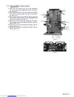
Page 13: ...sembly See Fig 18 2 Remove the one screw R attaching the Power trans board assembly See Fig 19 3 Disconnect the connector wire from Power cord connected to connector CN101 and disconnect the connector wire from Power transformer connected to connector CN102 of the Power trans board assembly See Fig 20 Fig 18 Fig 19 Fig 20 Q R CN101 CN102 ...

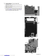
Page 14: ...e five screws S attaching the FL board assem bly 3 1 11 Removing the Key board assembly See Fig 21 1 Remove the Volume knob 2 Remove the six screws T attaching the Key board assem bly 3 Disengage the six hooks c engaged Key board assembly Fig 21 T T S S S hook c hook c hook c ...

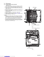
Page 15: ...lder the solder part of DVD pick up See Fig 5 6 Disconnect the card wire from CN101 and CN201 on the DVD module board See Fig 6 Caution Solder the short land section on the DVD pickup before dis connecting the card wire from the connector on the DVD pickup If the card wire is disconnected without attaching sol ders the pickup may be destroyed by static electricity When attaching the DVD pickup be ...

Page 16: ...1 16 No MB595 Fig 3 Fig 4 Fig 5 Fig 6 C C C C DVD module board D D Traverse mechanism assembly DVD mechanism assembly Solder short land section CN101 CN201 DVD module board ...

Page 17: ...crew from traverse mechanism assem bly See Fig 9 Caution When remove the lead screw do not loss the middle gear See Fig 10 and 11 4 Remove the bar spring pressing the shaft See Fig 10 5 Take out the pickup assembly from traverse mechanism chassis by order See Fig 11 Fig 7 Fig 8 Fig 9 Fig 10 Fig 11 ROD SPRING ROD SPRING E F Spring holder Lead screw Middle gear T TABLE HOOK SHAFT BAR SPRING order 1 ...

Page 18: ...ing the feed motor assem bly 2 Remove the feed motor wires from solder part of spindle motor board Fig 12 3 2 4 Removing the spindle motor assembly See Fig 13 1 Remove the two screws H attaching the spindle motor from spindle motor board Fig 13 Lead screw Middle gear Splder part G Spindle motor H ...

Page 19: ...e one screw K attaching the shaft guide from bottom side See Fig 14 3 Remove the two screws L attaching the shaft guide from top side See Fig 15 Caution When attach the tray assembly boss of loading sub assembly should attach to guide of bottom side at tray assembly See Fig 15 Fig 14 Fig 15 J order 1 order 2 clamper base K bottom side L ...

Page 20: ...Learned Y Y N Y Y N N N w Status 0 3 BLANK Initialize Status Normal Full Not Initialize T x x y v w No STEP NORMAL INITIALIZE FULL INITIALIZE 1 During DVD TEST MODE Press key on front panel Press STOP key on front panel and hold for 4 seconds 2 System display w status w 0 Normal initialize w 3 Full initialize 1 During TEST MODE press MENU key on remote control to enter DEVICE KEY CHECKSUM display ...

Page 21: ...perform SEARCH DVD_DL PARALLEL DISC DESIGNATED POSITION and JITTER MEASUREMENT 2 seconds Status AA 00 cc cc jj jj Static xi During CHECK mode press 0 key on REMOTE CONTROL to perform monitor output 2 seconds Status AA 00 cc cc jj jj Static xii During CHECK mode press 10 key to INITIALIZE DVD module EEPROM xiii During CHECK mode press PLAY key on REMOTE CONTROL to start PLAYING and obtain LASER CUR...

Page 22: ... No MB595 VPT Printed in Japan Victor company of Japan Limited Audio Video Systems category 10 1 1chome Ohwatari machi Maebashi city Gumma ken 371 8543 Japan ...

Page 23: ... 2 2 2 10 to 12 CD ROM No SML200702 MICRO COMPONENT SYSTEM No MB595SCH 2007 2 COPYRIGHT 2007 Victor Company of Japan Limited Lead free solder used in the board material Sn Ag Cu melting point 219 Centigrade CA UXG68 SUPER VIDEO SP UXG68 SP UXG68 Lead free solder used in the board material Sn Cu melting point 230 Centigrade ...

Page 24: ...ponent parts appearing on the silk screen printed side parts side of the PWB diagrams the parts that are printed over with black such as the resistor diode and ICP or identified by the mark nearby are critical for safety ...

Page 25: ... UCS SCLK U2SDT Q205 S2UDT SCS CPURST DVDPWR IC340 CONVERTER 3 3V to 5 5V CN203 FW213 CN207 CN217 CN209 CN210 CN220 CN219 REMOCON STANDBYLED FLCLK FLATCH FLDATA KEY1 KEY2 VOL SUB1 SUB2 SUB1 SUB2 ECO1 S1 S2 S3 S2CT Transformer section AC INPUT T102 TRANSFORMER RY101 RELAY S1 TRAY SWITCH LOADING MOTOR Loader section X302 IC303 48MHz 5V USB6V USB6V IC850 IC851 Q850 AUX AMP QP LINK CN803 CN811 CN851 F...

Page 26: ... TO CN201 OF GVA10111 A1 PAGE 2 6 50Hz UNLESS OTHERWISE SPECIFIED ALL INDUCTANCE VALUES ARE IN H m mH ALL CAPACITORS ARE CERAMIC CAPACITOR OR ALL RESISTORS ARE 1 4W 5 CARBON FILM RESISTOR ALL CAPACITANCE VALUES ARE IN F P pF ALL E CAPACITORS ARE SHOWN IN THE FORM OF MYLAR CAPACITOR ALL RESISTANCE VALUES ARE IN OHM CAPACITANCE F RATED VOLTAGE V OR 0 063W 5 THICK FILM CHIP RESISTOR 50Hz AC240V A U F...

Page 27: ... 5 47K R691 47K R697 10 35 C695 SQ 10p 50 C692 47K R694 IC690 KIA4558F X 8 7 6 5 4 3 2 1 10p 50 C693 10 35 C694 SQ C696 NI 47K R690 47K R695 R699 1K 47K R692 R698 1K 47K R696 C697 100 16 47K R693 0 R593 CN219 QGD2504C1 03Z 3 2 1 CN220 QGD2504C1 03Z 6 5 4 SYSTEM MUTE LIN LIN NC PRE VCC BIAS L L VCC R R PRE VCC SUBGND RIN RIN VCC INR R2 R1 UNF UNF KRC102M T C571 GVA10112 A1 1 4W 0V 0V 0V 36 6V 34 7V...

Page 28: ...6 2K R237 B2440 B2900 NI NI C297 CN207 1 2 3 4 5 6 7 8 9 10 11 12 13 14 15 16 17 18 19 20 21 CN206 QGD2504C1 03Z 1 2 3 KIA78D06PI U P IC270 1 2 3 FW209 QUM156 11DGZ4 EWIRE 6 5 4 3 2 1 DAVDD DAVSS ENDSW AV IN AV OUT EEP SCL EEP SDA GVA10111 A1 1 2 FROM CN1 OF FROM CN100 OF ALPS MECHA PULL HIGH 5V RECL A0 A1 RECR SLC8V PBL AGND PBR MOTOR MG VREF AV IN A2 GND VCC SDA SCL WP VSS VDD RESET PIN21 PIN22 ...

Page 29: ...24 NI R928 15K R917 100 16 C926 47P C903 GV40327 002A EP900 NI Q902 1K R906 K901 QQR0621 001Z 0 01 50 C914 K902 QQR0621 001Z 33 16 C900 10K R929 5 6K R922 47 50 C922 4 7 25 C909 1K R907 Q901 2SC3928A QR X QVQ0306 B24 VR900 B9101 NI D700 680 R705 NI C709 CN215 QGF1205F2 15 1 2 3 4 5 6 7 8 9 10 11 12 13 14 15 FW710 1 2 3 4 FW710 1 2 3 4 100 16 C907 K803 NI K804 NI K805 NI K806 NI NI K905 B9107 QUY15...

Page 30: ...CV IN MUTE1 C IN GND Y IN YC MIX Py G IN MUTE2 Pb B IN Pr R IN GND VCC1 CV OUT C OUT S DCOUT Y OUT GND Py G OUT Pb B OUT Pr R OUT GND GND SCREEN_MODE DAC1 Y G DAC3 R C Cr DAC5 C DAC4 Y Comp 5V AUDIO ROUT AUDIO RIN AUDIO LOUT AUDIO LIN AUDIO AGND GND GND GND GND GND GND GND NC NC B G R C BLANKING FUNCTION COMPOSITE Y SCART TERMINAL COMPONENT VIDEO OUT NC Py G OUT SAG Pb B OUT SAG Pr R OUT SAG CV OU...

Page 31: ...23 EXADT13 24 EXADT12 25 EXADT11 26 EXADT10 27 EXADT9 28 EXADT8 29 EXADR19 30 NEXWE 31 VSS 32 VDD33 33 EXADR18 34 EXADR17 35 EXADT7 36 EXADT6 37 EXADT5 38 EXADT4 39 EXADT3 40 EXADT2 41 EXADT1 42 VSS 43 VDD12 44 EXADR20 45 S0OUT 46 S0CLK 47 INT0 48 S1OUT 49 P5 50 VSS 51 VDD33 52 S2IN 53 S2OUT 54 S2CLK 55 P9 56 S3OUT 57 S3CLK 58 P12 59 P13 60 P14 61 DRV5 62 DRV4 63 DRV3 64 DRV2 65 DRV1 66 DRV0 67 VS...

Page 32: ...P719 0 1 C554 1 C562 F NI R740 K755 NI TP723 IC505 K4S641632K UC75 27 VDD 28 VSS 29 A4 30 A5 31 A6 32 A7 33 A8 34 A9 35 A11 36 NC 37 CKE 38 CLK 39 UDQM 40 NC RFU 41 VSS 42 DQ8 43 VDDQ 44 DQ9 45 DQ10 46 VSSQ 47 DQ11 48 DQ12 49 VDDQ 50 DQ13 51 DQ14 52 VSSQ 26 A3 25 A2 24 A1 23 A0 22 A10 AP 21 BA1 20 BA0 19 CS 18 RAS 17 CAS 16 WE 15 LDMQ 14 VDD 13 DQ7 12 VSSQ 11 DQ6 10 DQ5 9 VDDQ 8 DQ4 7 DQ3 6 VSSQ 5...

Page 33: ... 5V VSS VDD OUT NC UN2113X OR LVA10626 611B 3 3 6V 0V 0V 0V 0V ALL RESISTORS ARE 1 16W 5 METAL GLAZE RESISTOR OR 0 5 METAL GLAZE RESISTOR ALL INDUCTANCE VALUES ARE IN H m mH UNLESS OTHERWISE SPECIFIED NOTES 47k 2 CONDITION A DVD disc in the Tray 1 and STOP mode NI STANDS FOR NOT INSERTED PARTS UN2113 X ALL CAPACITANCE VALUES ARE IN F p pF ALL CAPACITORS ARE 50V 25V 16V 10V or 6 3V CERAMIC CAPACITO...

Page 34: ...50 R252 R253 R263 R261 R260 R270 R240 Q260 CN831 C314 IC301 R360 R332 R333 R334 R335 R305 R304 R359 C212 R317 R316 R315 R336 R337 C340 C365 C366 R365 R349 D227 R357 R358 Q220 Q221 R280 R285 C452 C409 Q480 C453 R481 C403 C402 C401 R403 R402 R401 C400 C455 R478 R475 R474 R473 R479 R470 R471 R472 R404 R410 C454 R477 R476 IC450 R411 R406 J403 R480 C451 C450 R418 R419 R422 R423 R408 C405 C407 R432 R433...

Page 35: ...619 C609 R611 R617 C634 R643 R645 Q661 C641 R697 C695 C692 R694 C694 C625 R695 R692 R696 R693 R691 IC690 C693 R690 Q642 Q500 R539 R534 C661 C662 R664 R660 C663 C660 R661 Q660 K660 R662 C665 R669 R665 R663 B6001 C572 CN811 W502 C577 C578 C576 C575 C571 Q550 CN810 R542 R541 R567 R568 R563 R562 R561 R560 Q580 CN722 R681 Q581 C680 R680 R595 C670 Q670 C671 R670 R651 R650 R543 RY550 EP500 R654 C650 Q506...

Page 36: ... TP743 CN703 R723 TP742 R715 C558 K501 C740 R535 K704 C743 TP735 C559 TP744 R725 IC702 TP733 TP710 K706 TP745 TP708 K701 C703 TP752 C382 TP714 TP720 TP737 TP713 TP751 R530 R730 C560 C701 TP761 TP719 C554 C562 R740 TP723 IC505 R531 CN712 TP727 TP726 TP467 R811 R814 R813 R812 TP803 CN801 K811 K812 R861 TP802 TP801 TP812 TP811 TP813 D811 D812 IC891 R891 R892 C891 R860 TP819 R819 C819 R129 R378 R379 R...

Page 37: ... M E M O ...
Page 38: ...Victor Company of Japan Limited No MB595SCH Printed in Japan VPT Audio Video Systems Category 10 1 1chome Ohwatari machi Maebashi city 371 8543 Japan ...

Page 39: ...ploded view of general assembly and parts list Block No M1 DVD mechanism assembly and parts list Block No MJ DVD loading base assembly and parts list Block No MN Electrical parts list Block No 01 04 Packing materials and accessories parts list Block No M3 UX G68E UX G68EN UX G68EV 3 2 3 6 3 8 3 10 3 16 MB595 ...

Page 40: ...arts list E E F a j k m s Power amplifier board Jack board Switch board FL board P bo Block No M M M 1 K 2 12 1 15 15 28 28 7 6 13 14 13 8 3 9 4 5 25 20 20 19 51 34 33 39 36 29 61 61 62 62 63 63 63 63 63 57 11 11 11 10 10 16 82 60 79 77 77 78 76 ...

Page 41: ... amplifier board Main board ck board h board Power supply board M M M 1 n B 27 37 67 50 43 56 49 53 44 44 45 46 47 48 55 80 52 25 20 20 19 51 54 81 41 42 34 34 73 32 74 31 31 30 65 33 39 23 24 24 38 38 35 40 26 36 29 1 11 11 10 10 16 82 59 66 22 69 70 72 18 17 21 71 68 79 77 78 75 64 58 ...

Page 42: ...010ZA TAP SCREW M3 x 10mm x2 35 GV30915 001A BRACKET B 36 GV30349 057A SPACER 37 QYSBSGG3008EA TAP SCREW M3 x 8mm 38 GV40613 002A SPACER x3 39 GV30349 018A SPACER 40 QYSBST4006ZA TAP SCREW M4 x 6mm 41 GV20410 015A REAR PANEL 42 GV30855 001A HEAT SINK 43 GV30850 001A FAN BRACKET 44 QYSBSGY3008EA TAP SCREW M3 x 8mm x2 45 QYSBSGY3008EA TAP SCREW M3 x 8mm x2 46 QYSBSGY3008EA TAP SCREW M3 x 8mm 47 QYSB...

Page 43: ...x2 77 GV40680 001A FL HOLDER A x2 78 GV40683 001A FL HOLDER B 79 GV40557 001A LED HOLDER 80 QUQU12 1516BJ E FFC WIRE FC11 15pin 16cm 81 QUQU12 1319BJ E FFC WIRE FC217 13pin 19cm 82 QUQU12 1509BJ E FFC WIRE FC205 15pin 9cm Symbol No Part No Part Name Description Local ...

Page 44: ...parts list Grease 1401C JVS 1003 JVG 31N Back side The parts without symbol number are not service FXL D10 1M 7 0mm 0 2mm Block No M M M J 17 31 25 30 20 14 15 31 31 23 22 24 29 28 26 27 16 18 3 13 11 1 6 12 7 21 9 8 31 4 5 10 2 30 3 ...

Page 45: ...12 QYSPSPT2030MA SCREW M2 x 3mm 13 QYSDST2005ZA TAP SCREW M2 x 5mm 14 QAL0786 002 P UP 15 LV22237 001A RACK ARM 16 LV36560 001A RACK ARM SPRING 17 QYSPSFU1740ZA TAP SCREW M1 7 x 4mm x2 18 QUQK05 2415AC E FFC WIRE 24pin 15cm 20 LV44041 002A GUIDE SHAFT 21 LV36559 001A L S GEAR 22 LV41517 003A LEAD SCREW 23 LV36558 001A MIDDLE GEAR 24 LV36556 001A SPRING HOLDER 25 LV44623 001A COMP SPRING 26 QYSDST2...

Page 46: ...No M M M N 7 75mm 0 10mm h h FMU MB6 11M Backside The parts without symbol number are not service DVD module board Back side j A B e f c d j c d e f DVD loading switch board A B 16 12 15 8 19 18 20 10 9 16 17 4 23 23 3 2 6 1 14 11 27 22 22 13 7 5 21 24 25 26 26 25 25 25 23 22 ...

Page 47: ... 10 LV43844 002A MOTOR PULLEY 11 QYSPSPU1730ZA SCREW M1 7 x 3mm x2 12 QYSDSF2008ZA TAP SCREW M2 x 8mm 13 LV43974 001A BELT 14 LV21852 003A CLAMPER BASE 15 QYSDSF2008ZA TAP SCREW M2 x 8mm x2 16 LV41741 004A SPECIAL SCREW 17 LV35056 002A DVD CLAMPER 18 LV42930 003A P C MAGNET 18 or LV41118 003A MAGNET 19 LV43848 001A YOKE 20 LE40906 002A SPECIAL SCREW 21 SINGLE DVD TRAM 22 LV44043 001A INSULATOR x4 ...

Page 48: ...4 QETN1HM 226Z E CAPACITOR 22uF 50V M C225 QETN1HM 106Z E CAPACITOR 10uF 50V M C230 NCB31HK 103X C CAPACITOR 0 01uF 50V K C231 NCB31HK 221X C CAPACITOR 220pF 50V K C241 QETN1EM 476Z E CAPACITOR 47uF 25V M C251 QETN1EM 476Z E CAPACITOR 47uF 25V M C261 QETN1CM 107Z E CAPACITOR 100uF 16V M C271 QETN0JM 108Z E CAPACITOR 1000uF 6 3V M C281 QETN1EM 476Z E CAPACITOR 47uF 25V M C295 QETN1CM 107Z E CAPACIT...

Page 49: ... MG RESISTOR 10kΩ 1 16W J R363 NRSA63J 103X MG RESISTOR 10kΩ 1 16W J Symbol No Part No Part Name Description Local R365 NRSA63J 101X MG RESISTOR 100Ω 1 16W J R366 NRSA63J 104X MG RESISTOR 100kΩ 1 16W J R370 NRSA63J 102X MG RESISTOR 1kΩ 1 16W J R372 NRSA63J 104X MG RESISTOR 100kΩ 1 16W J R374 NRSA63J 103X MG RESISTOR 10kΩ 1 16W J R390 NRSA63J 123X MG RESISTOR 12kΩ 1 16W J R391 NRSA63J 123X MG RESIS...

Page 50: ... 50V J C509 QETN1VM 476Z E CAPACITOR 47uF 35V M C510 NCB31HK 104X C CAPACITOR 0 1uF 50V K C511 NCB31HK 104X C CAPACITOR 0 1uF 50V K C517 QETN1HM 106Z E CAPACITOR 10uF 50V M C518 NDC31HJ 101X C CAPACITOR 100pF 50V J C519 NCB31HK 104X C CAPACITOR 0 1uF 50V K C520 NCB31HK 104X C CAPACITOR 0 1uF 50V K C521 NDC31HJ 5R0X C CAPACITOR 5pF 50V J C522 QETN1VM 476Z E CAPACITOR 47uF 35V M C523 QETN1HM 226Z E ...

Page 51: ...16W J R602 NRSA63J 103X MG RESISTOR 10kΩ 1 16W J R603 NRSA63J 302X MG RESISTOR 3kΩ 1 16W J R604 NRSA63J 244X MG RESISTOR 240kΩ 1 16W J R605 NRSA63J 244X MG RESISTOR 240kΩ 1 16W J R611 NRSA63J 752X MG RESISTOR 7 5kΩ 1 16W J R612 NRSA63J 222X MG RESISTOR 2 2kΩ 1 16W J R613 NRSA63J 302X MG RESISTOR 3kΩ 1 16W J R621 NRSA63J 752X MG RESISTOR 7 5kΩ 1 16W J R622 NRSA63J 222X MG RESISTOR 2 2kΩ 1 16W J R62...

Page 52: ...K 104X C CAPACITOR 0 1uF 16V K C375 NCB31CK 104X C CAPACITOR 0 1uF 16V K Symbol No Part No Part Name Description Local C378 NCB31CK 104X C CAPACITOR 0 1uF 16V K C379 NCB31CK 104X C CAPACITOR 0 1uF 16V K C380 NCB21CK 105X C CAPACITOR 1uF 16V K C381 NCB21AK 225X C CAPACITOR 2 2uF 10V K C382 NCB31HK 471X C CAPACITOR 470pF 50V K C383 NCB31CK 104X C CAPACITOR 0 1uF 16V K C391 NEAF0JM 227X E CAPACITOR 2...

Page 53: ...16W J R705 NRSA63J 0R0X MG RESISTOR 0Ω 1 16W J R718 NRSA63J 473X MG RESISTOR 47kΩ 1 16W J R721 NRSA63J 471X MG RESISTOR 470Ω 1 16W J R722 NRSA63J 0R0X MG RESISTOR 0Ω 1 16W J R723 NRSA63J 471X MG RESISTOR 470Ω 1 16W J R730 NRSA63J 331X MG RESISTOR 330Ω 1 16W J R731 NRSA63J 102X MG RESISTOR 1kΩ 1 16W J R732 NRSA63J 102X MG RESISTOR 1kΩ 1 16W J R811 NRS181J 330X MG RESISTOR 33Ω 1 8W J R812 NRS181J 33...

Page 54: ...3 16 Packing materials and accessories parts list Block No M M M 3 No additional supplemental order of WARRANTY CARDs are available A9 A10 A10 A8 P8 P9 P10 P11 P3 P5 A6 P7 P6 P1 P4 P2 A2 A1 A5 A3 A4 A7 ...

Page 55: ...V30898 001A I B LABEL A 6 RM SUXG60R REMOCON A 7 BATTERY 1 5V x2 A 8 SPUXG68E SPBOX SPK WITH BOX x2 A 9 ASW803262 0020 SPK NET ASSY x2 A10 BRF800017 0002 RUBBER CUSHION x8 P 1 GV30994 001A CARTON ASSY P 2 QPC01702515PB POLY BAG 17cm x 25cm P 3 GV40437 004A CLOTH P 4 QPC02503515PB POLY BAG 25cm x 35cm P 5 QPC05006515PB POLY BAG 50cm x 65cm P 6 GV10306 001A CUSHION UPPER P 7 GV10307 001A CUSHION BOT...

Reviews: