1-10 (No.MB542)
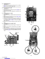
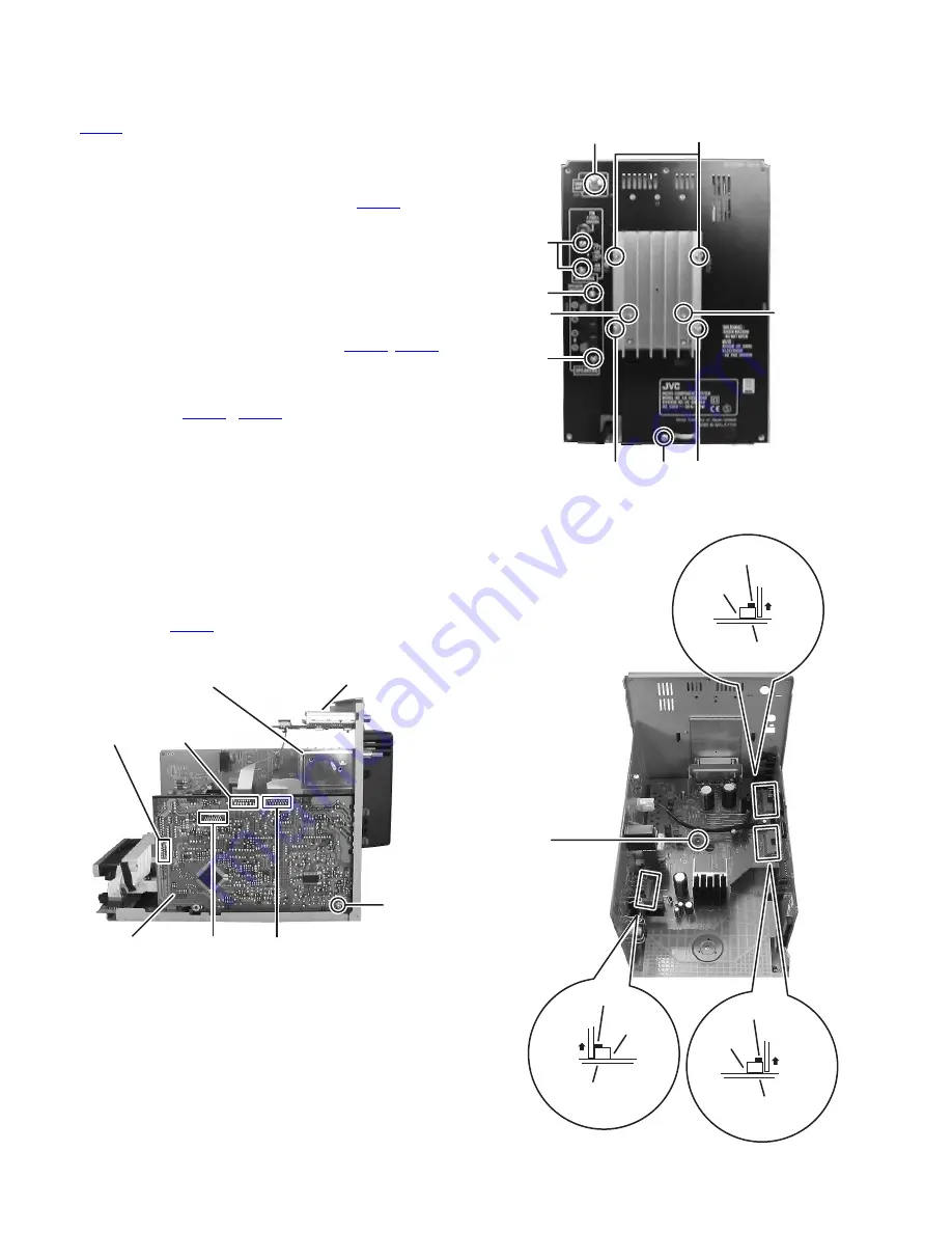
3.1.3 Removing the tuner
(See Fig.5, 6)
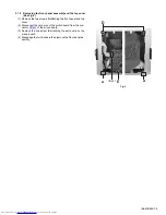
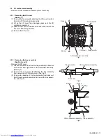
(1) Disconnect the card wire of the tuner from connector
CN405
of the micon board. (See Fig.5)
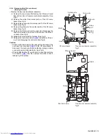
(2) Remove the two screws
F
attaching the tuner. (See Fig.6)
3.1.4 Removing the tuner pack
(See Fig.5, 6)
(1) Disconnect the card wire from the connector
CN408
of the
micon board. (See Fig.5)
(2) Remove the one nut
G
attaching the tuner pack. (See
Fig.6)
3.1.5 Removing the micon board
(See Fig.5 to7)
(1) Remove the two screws
H
attaching the micon board. (See
Fig.6)
(2) Disconnect the card wires from connectors
CN400
,
CN406
of the micon board. (See Fig.5)
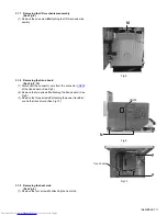
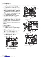
(3) Disconnect the micon board from the power amplifier board
in the direction of the arrow while releasing the claw
b
,
c
of
the connectors
CN151
,
CN152
on the power amplifier
board. (See Fig.7)
(4) Remove the one screw
J
attaching the micon board. (See
Fig.5)
3.1.6 Removing the power amplifier board
(See Fig.6, 7)
(1) Remove the two screws
K
attaching the IC bracket. (See
Fig.6)
(2) Remove the one screw
L
attaching the power amplifier
board. (See Fig.7)
(3) Disconnect the power amplifier board from the trans board
in the direction of the arrow while releasing the claw
d
of
the connector
CN150
on the power amplifier board. (See
Fig.7)
Fig.5
Fig.6
Fig.7
CN405
CN406
CN408
Micon board
Tuner
Tuner pack
CN400
J
F
G
H
H
K
K
Q
Q
Q
R
CN151
power amplifier
board
b
L
CN152
power amplifier
board
c
power amplifier
board
CN150
d
Summary of Contents for UX-GB9DABB
Page 35: ... M E M O ...

