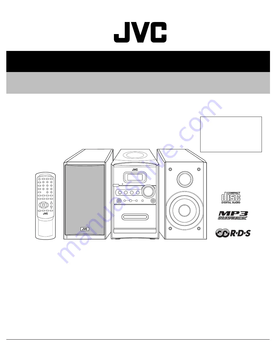
background image

SERVICE MANUAL

COPYRIGHT © 2004 Victor Company of Japan, Limited

No.MB215

2004/6

MICRO COMPONENT SYSTEM

MB215

2004

6

UX-H330, UX-H300

TABLE OF CONTENTS

1

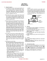
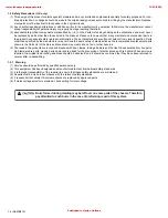
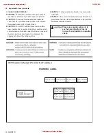
PRECAUTION. . . . . . . . . . . . . . . . . . . . . . . . . . . . . . . . . . . . . . . . . . . . . . . . . . . . . . . . . . . . . . . . . . . . . . . . .  1-3

2

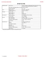
SPECIFIC SERVICE INSTRUCTIONS . . . . . . . . . . . . . . . . . . . . . . . . . . . . . . . . . . . . . . . . . . . . . . . . . . . . . .  1-7

3

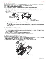
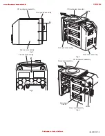
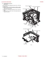
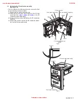
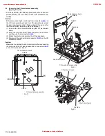
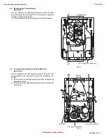
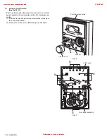
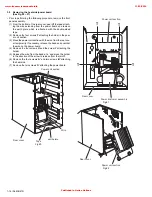
DISASSEMBLY  . . . . . . . . . . . . . . . . . . . . . . . . . . . . . . . . . . . . . . . . . . . . . . . . . . . . . . . . . . . . . . . . . . . . . . .  1-8

4

ADJUSTMENT . . . . . . . . . . . . . . . . . . . . . . . . . . . . . . . . . . . . . . . . . . . . . . . . . . . . . . . . . . . . . . . . . . . . . . .  1-19

5

TROUBLESHOOTING . . . . . . . . . . . . . . . . . . . . . . . . . . . . . . . . . . . . . . . . . . . . . . . . . . . . . . . . . . . . . . . . .  1-21

Area suffix

B ------------------------------ U.K.
E ---------- Continental Europe
EN ----------- Northern Europe
EV ------------- Eastern Europe

www.freeservicemanuals.info

13/10/2016

Published in Heiloo Holland

Summary of Contents for UX-H300

Page 1: ... MB215 2004 6 UX H330 UX H300 TABLE OF CONTENTS 1 PRECAUTION 1 3 2 SPECIFIC SERVICE INSTRUCTIONS 1 7 3 DISASSEMBLY 1 8 4 ADJUSTMENT 1 19 5 TROUBLESHOOTING 1 21 Area suffix B U K E Continental Europe EN Northern Europe EV Eastern Europe www freeservicemanuals info 13 10 2016 Published in Heiloo Holland ...

Page 2: ...r Dynamic range 85 dB Signal to noise ratio 85 dB Wow and flutter Immeasurable Cassette deck Frequency response Normal type I 100 Hz 10 000 Hz Wow and flutter 0 35 WRMS General Power requirement AC 230 V 50 Hz Power consumption 40 W at operation 2 W on standby Dimensions W H D approx 152 mm 233 mm 292 mm Mass approx 3 9 kg Speaker Section Type Full range bass reflex type Speakers 10 cm cone 1 Powe...

Page 3: ... the product is safe to operate without danger of electrical shock Do not use a line isolation transformer during this check Plug the AC line cord directly into the AC outlet Using a Leakage Current Tester measure the leakage current from each exposed metal parts of the cabinet particular ly any exposed metal part having a return path to the chassis to a known good earth ground Any leakage cur ren...

Page 4: ... recommended replacement parts shown in the Parts List of the Service Manual and may create shock fire or other hazards 4 The leads in the products are routed and dressed with ties clamps tubings barriers and the like to be separated from live parts high temperature parts moving parts and or sharp edges for the prevention of electric shock and fire hazard When service is required the original lead...

Page 5: ...pickup The tester s internal power source can easily destroy the laser diode 1 7 Handling the traverse unit optical pickup 1 Do not subject the traverse unit optical pickup to strong shocks as it is a sensitive complex unit 2 Cut off the shorted part of the flexible cable using nippers etc after replacing the optical pickup For specific details refer to the replacement procedure in the text Remove...

Page 6: ...CT EXPOSURE TO BEAM e VARNING Synlig och osynling laserstrålning när den öppnas och spärren är urkopplad Betrakta ej strålen s VARO Avattaessajasuojalukitus ohitettuna tai viallisena olet alttiina näkyvälle ja näkymättömälle lasersäteilylle Vältä säteen kohdistumista suoraan itseesi f ADVARSEL Synlig og usynlig laserstråling når maskinen er åben eller interlocken fejeler Undgå direkte eksponering ...

Page 7: ... No MB215 1 7 SECTION 2 SPECIFIC SERVICE INSTRUCTIONS This service manual does not describe SPECIFIC SERVICE INSTRUCTIONS www freeservicemanuals info 13 10 2016 Published in Heiloo Holland ...

Page 8: ...body 3 Remove the screw E on the bottom of the body 4 Move the front panel assembly in the direction of the arrow and remove Disconnect connector CN402 CN801 on the main board Caution When reassembling the front panel assembly fit the right and left tabs a to the notch Fig 1 Fig 2 CD mechanism assembly Rear cover assembly B H A Front panelh assembly CD mechanism assembly Rear cover assembly D www ...

Page 9: ...ar panel assembly D Front panel assembly Rear panel assembly E CD mechanism assembly Front panel assembly Rear cover assembly Joint a CD mechanism assembly Front panel assembly Main board Rear cover assembly CN402 CN801 www freeservicemanuals info 13 10 2016 Published in Heiloo Holland ...

Page 10: ...s on the cas sette mechanism assembly 3 Release the three bands attaching the wire to the main board 4 Remove the two screws F from the front panel assembly Release the joint b Fig 7 Fig 8 CD mechanism assembly CD mechanism assembly Front panel assembly CN203 Main board CN303 CN602 CN301 CN401 CN603 CN103 Main board band CD mechanism assembly Front panel assembly b F www freeservicemanuals info 13...

Page 11: ...from CN601 CN603 and CN604 on the CD mechanism board respectively 3 Remove the three screws G attaching the CD mechanism assembly 4 Release the joint d to remove the CD mechanism assem bly from the front panel assembly Fig 9 Fig 10 CD mechanism assembly CD door switch CD mechanism board Front panel assembly CN604 CN603 CN601 Band Band Band G G G CD mechanism assembly Front panel assembly Joint d J...

Page 12: ...CD mechanism board 2 Move the CD mechanism board temporarily and discon nect the wire from connector CN606 3 Solder the short circuit point on the CD pickup board 4 Disconnect the card wire from connector CN607 on the CD mechanism board Caution Make sure to unsolder the short circuit point after reconnecting the card wire to the CD pickup board and to connector CN607 on the CD mechanism board Fig ...

Page 13: ...he headphone board AUX board See Fig 15 Prior to performing the following procedure remove the front panel assembly the main board and the CD mechanism as sembly 1 Remove the screw K attaching the bracket and detach the headphone board 2 Remove the screw M attaching the bracket and detach the AUX board Fig 15 CD mechanism assembly CD mechanism J J Front panel assembly AUX board Head phones board B...

Page 14: ...n board and the CD mechanism as sembly 1 From the front panel pull out the volume knob and remove the nut and the washer 2 Remove the twelve screws N attaching the LCD board Fig 16 Fig 17 Front panel assembly Washer Volume konb Nat Front panel assembly LCD board N N N N www freeservicemanuals info 13 10 2016 Published in Heiloo Holland ...

Page 15: ...ont panel to open the cassette door 2 Remove the screw P attaching the bracket of the cassette mechanism assembly 3 Remove the two screws Q and the two screws R attaching the cassette mechanism assembly Fig 18 Fig 19 Front panel assembly Cassette door PUSH OPEN Cassette mechaanism assembly Front panel assembly Bracket Q Q R R P www freeservicemanuals info 13 10 2016 Published in Heiloo Holland ...

Page 16: ...e from the rear cov er temporarily If necessary release the band and unsolder the wire on the power board 4 Remove the four screws U and the screw Y attaching the holder 5 Release the wire from the band at e and move the holder in the direction of the arrow to release from the joint f 6 Remove the four screws A and two screws B attaching the heat sink 7 Remove the two screws D attaching the power ...

Page 17: ...Power board Band Heat sink Holder Y Power board Power board Band Band e Band Heat sink Unsolder Unsolder Unsolder Joint f A B Heat sink Power board A A Heat sink Power board D Bracket Power board www freeservicemanuals info 13 10 2016 Published in Heiloo Holland ...

Page 18: ...our screws E attaching the power transform er assembly The bracket comes off at the bottom of the rear cover 2 Remove the screw F attaching the power cord folder 3 Remove the two screws G attaching the AC connect board Fig 28 Fig 29 Rear cover E E Power trnsfomer assembly Rear cover F G G Power cord folder AC connect board www freeservicemanuals info 13 10 2016 Published in Heiloo Holland ...

Page 19: ...ness 3kHz VT724 Reference level 1kHz 8 Blank tape TYPE AC 225 TYPE AC 514 9 Torque gauge For play and back tension FWD TW2111A REV TW2121a and FF REW TW2231A 10 Test disc CTS 1000 4 2 Measurement conditons 4 3 Radio Input signal Power supply voltage AC230V AC240V 50Hz 60Hz Reference output Speaker 0 dB 2V 4 Ω Headphone 10 dB 0 245V 32Ω Reference frequency and input level 1kHz AUX 8dBs Measurement ...

Page 20: ...o 3090 Hz within 0 38 unweighted Tape speed Motor semifixed resistor REC and PB frequency response adjustment Test tape VT703L Signal input FM 22 5 DEV 60dB with Emphasis Signal output terminal PHONES with 32 ohm load At TUNER set the BAND to the FM position and record the reference 1 kHz signal and 10kHz signal alternately repeatedly While playing back the recorded signal differ from that of the ...

Page 21: ...ages Replace if necessary Intermediate Frequency tuning faulty Readjust see Alignment and Adjustment Poor contact in FM antenna circuit Resolder or repair as required Tape Dirty capstan or head Clean the capstan or head with alcohol Irregular cassette tape winding Replace tape Defective IC201 Check voltage Replace if necessary Cassette erasure prevention tabs broken out Replace tape or cover tab o...

Page 22: ...IMEDIA COMPANY AUDIO VIDEO SYSTEMS CATEGORY 10 1 1chome Ohwatari machi Maebashi city 371 8543 Japan Victor Company of Japan Limited WPC Printed in Japan www freeservicemanuals info 13 10 2016 Published in Heiloo Holland ...

Page 23: ... of general assembly and parts list Block No M1 Electrical parts list Block No 01 04 Packing materials and accessories parts list Block No M3 UX H330 UX H300 3 2 3 6 3 16 Area suffix B U K E Continental Europe EN Northern Europe EV Eastern Europe MB215 www freeservicemanuals info 13 10 2016 Published in Heiloo Holland ...

Page 24: ...hone board Power board AC conntact board F901 F902 71 73 53 22 23 74 24 25 72 26 27 73 28 29 29 30 32 29 31 33 34 35 36 37 38 39 40 46 20 72 75 92 93 71 42 41 76 77 72 72 47 85 48 49 50 51 52 71 73 71 58 71 59 60 78 61 73 72 79 79 86 79 62 94 65 66 81 81 8 66 www freeservicemanuals info 13 10 2016 Published in Heiloo Holland ...

Page 25: ... LED board Main board board Power board AC conntact board F901 F902 72 18 72 20 71 73 73 80 53 22 23 74 24 25 72 26 27 73 28 29 29 30 29 31 46 2 75 92 93 71 77 72 72 47 85 48 49 50 51 52 71 73 71 58 71 59 60 78 61 73 72 79 79 86 79 84 76 62 64 94 65 66 66 66 65 67 82 90 81 81 81 66 www freeservicemanuals info 13 10 2016 Published in Heiloo Holland ...

Page 26: ... 38 OW53 00300 13 VOLUME KNOB 39 OW43 00300 22 DISPLAY LENS 40 OW53 00300 14 SNOOZE KNOB 41 OW48 00300 19 SNOOZE KNOB BKT 42 OW53 00300 12 POWER KNOB 46 OW53 00300 10 FUNCTION KNOB A 47 OW91 80300 00 LCD DISPLAY G9419TT P 48 OW43 00300 20 LCD FILTER 49 OW48 00300 13 PCB BKT MAIN 50 OW43 00300 23 LIGHT GUIDE 51 OW68 00300 10 LCD FILTER PAPER 52 OW68 00300 12 FELT BLK 53 OW48 00300 10 LCD BKT 55 OW3...

Page 27: ...40007 80 STEEL NUT M3 88 OW35 20001 80 TOOTH WASHER M3 89 OW35 30005 80 SOLDERING LUG F3 5 L 9 90 OW30 00300 02 AC CORD SF 629 H03VVH2 F B 90 OW30 00300 01 AC CORD 2M SF 103 W SOLDER E EN EV 92 OW33 57162 03W FUSE 250V 1 6A F901 93 OW33 57632 03W FUSE 250V 6 3A F902 94 OW40 92610 01 SCREW M2 6 X 10 x2 B EV Symbol No Part No Part Name Description Local www freeservicemanuals info 13 10 2016 Publish...

Page 28: ...OW02 04148 81 D202 IN4148 DIODE OW02 04148 81 D302 IN4148 DIODE OW02 04148 81 D401 IN4148 DIODE OW02 04148 81 D402 IN4148 DIODE OW02 04148 81 D403 1N4001 DIODE OW02 04001 81 D404 IN4148 DIODE OW02 04148 81 D441 IN4148 DIODE OW02 04148 81 D442 IN4148 DIODE OW02 04148 81 D705 KL 3M4 LED OW02 30005 80 Blue D706 KL 3M4 LED OW02 30005 80 Blue C101 OW06 71477 20 E CAPACITOR 470mF 16V E EN C101 OW05 7010...

Page 29: ...F 50V C218 OW06 75105 20 E CAPACITOR 1mF 50V C219 OW05 73102 00 C CAPACITOR 1000pF B EV C220 OW05 73102 00 C CAPACITOR 1000pF B EV Symbol No Part No Part Name Description Local C221 OW06 75475 20 E CAPACITOR 4 7mF 50V C222 OW06 75475 20 E CAPACITOR 4 7mF 50V C223 OW05 73102 00 C CAPACITOR 1000 pF C224 OW05 73102 00 C CAPACITOR 1000 pF C225 OW05 73151 05 C CAPACITOR 150pF C226 OW05 73151 05 C CAPAC...

Page 30: ...ocal R124 OW07 75223 06 C RESISTOR 22K 1 16W E EN R124 OW07 75473 06 C RESISTOR 47K 1 16W B EV R125 OW07 75102 06 C RESISTOR 1K 1 16W E EN R125 OW07 75103 06 C RESISTOR 10K 1 16W B EV R126 OW07 75104 06 C RESISTOR 100K 1 16W E EN R126 OW07 75473 06 C RESISTOR 47K 1 16W B EV R127 OW07 75102 06 C RESISTOR 1K 1 16W E EN R127 OW07 75223 06 C RESISTOR 22K 1 16W B EV R128 OW07 75562 06 C RESISTOR 5 6K 1...

Page 31: ... R317 OW07 75222 06 C RESISTOR 2 2K 1 16W Symbol No Part No Part Name Description Local R318 OW07 75222 06 C RESISTOR 2 2K 1 16W R327 OW07 75222 06 C RESISTOR 2 2K 1 16W R328 OW07 75222 06 C RESISTOR 2 2K 1 16W R330 OW07 74100 50T C RESISTOR 10 1 8W R331 OW07 75103 06 C RESISTOR 10K 1 16W R333 OW07 74103 50T C RESISTOR 10K 1 8W R334 OW07 74103 50T C RESISTOR 10K 1 8W R401 OW07 75103 06 C RESISTOR ...

Page 32: ...0 UL WIRE 40mm BLK B EV TIEIE3 OW31 50040 80 UL WIRE 40mm BLK B EV TIEIE4 OW31 50040 80 UL WIRE 40mm BLK TIEIE5 OW31 50040 80 UL WIRE 40mm BLK E EN TIEIE6 OW31 50040 80 UL WIRE 40mm BLK TIEIE7 OW31 50040 80 UL WIRE 40mm BLK E EN Symbol No Part No Part Name Description Local TIEIE8 OW31 50040 80 UL WIRE 40mm BLK E EN VD101 SVC201 TUNING DIODE OW02 00201 81 B EV VD102 SVC201 TUNING DIODE OW02 00201 ...

Page 33: ...W05 73102 00 C CAPACITOR 1000pF C713 OW05 73240 05 C CAPACITOR 24pF C714 OW05 73560 05 C CAPACITOR 56pF C715 OW05 73240 05 C CAPACITOR 24pF C716 OW05 73120 05 C CAPACITOR 12pF E EN C716 OW05 73200 05 C CAPACITOR 20pF B EV C717 OW05 73120 05 C CAPACITOR 12pF E EN C717 OW05 73200 05 C CAPACITOR 20pF B EV C718 OW06 70476 81 E CAPACITOR 47mF 10V C721 OW06 70107 81 E CAPACITOR 100mF 10V C722 OW06 70476...

Page 34: ...ACT SWITCH Evqjae 05R SW709 OW16 10101 80 TACT SWITCH Evqjae 05R SW710 OW16 10101 80 TACT SWITCH Evqjae 05R X701 OW09 50720 80 CER RESONATOR ZTA7 2MT X702 OW04 32768 80 CRYSTAL 32 768 MHz X771 OW04 04332 80 CRYSTAL 4 332MHz Symbol No Part No Part Name Description Local XXXXX OW08 04344 21 FERRITE CORE For CN703 E EN XXXXX OW11 80300 03 DISPLAY PCB XXXXX OW84 00003 80 CABLE TIE 4 UL XXXXX OW84 0000...

Page 35: ... C RESISTOR 220 1 16W R605 OW07 75330 06 C RESISTOR 33 1 16W R606 OW07 75472 06 C RESISTOR 4 7K 1 16W R607 OW07 75472 06 C RESISTOR 4 7K 1 16W R608 OW07 75472 06 C RESISTOR 4 7K 1 16W R609 OW07 75472 06 C RESISTOR 4 7K 1 16W R610 OW07 75472 06 C RESISTOR 4 7K 1 16W R611 OW07 75100 06 C RESISTOR 10 1 16W R612 OW07 75100 06 C RESISTOR 10 1 16W R613 OW07 75100 06 C RESISTOR 10 1 16W R614 OW07 75472 0...

Page 36: ...OW07 75001 05F C RESISTOR 0 1 8W J663 OW07 75001 05F C RESISTOR 0 1 8W J664 OW07 75001 05F C RESISTOR 0 1 8W J665 OW07 75001 05F C RESISTOR 0 1 8W J666 OW07 75001 05F C RESISTOR 0 1 8W J667 OW07 75000 06 C RESISTOR 0 1 16W J668 OW07 75001 05F C RESISTOR 0 1 8W J669 OW07 75001 05F C RESISTOR 0 1 8W J670 OW07 75001 05F C RESISTOR 0 1 8W J671 OW07 75000 06 C RESISTOR 0 1 16W J672 OW07 75000 06 C RESI...

Page 37: ...3 15 MEMO www freeservicemanuals info 13 10 2016 Published in Heiloo Holland ...

Page 38: ...3 16 Packing materials and accessories parts list Block No M M M 3 P1 P2 P3 P4 P5 P6 P7 P8 P9 A1 A2 A3 A5 A6 A4 P5 P10 P11 P12 A7 www freeservicemanuals info 13 10 2016 Published in Heiloo Holland ...

Page 39: ...D H330B H330EV A 7 OW29 21400 80 FM ANT WIRE E EN P 1 OW89 00300 12 CARTON BOX H300E H300EN P 1 OW89 00300 04 CARTON BOX H300B H300EV P 1 OW89 00330 00 CARTON BOX H330 P 2 OW89 00300 02 CORRUGATED PAPER P 3 OW85 91014 82 POLY BAG 10 X 14 P 4 OW85 90710 84 POLY BAG 7 X 10 P 5 OW85 00025 81A POLY BAG 3 5 X 10 x2 P 6 OW81 01000 80 TURN TABLE CUSHION 116 X 17 X 2MM P 7 OW89 09023 80 CD PROTECT BOARD P...

Page 40: ...PAN LTD UX H330 UX H300 CD ROM No SML200406 Contents Wiring diagram 2 1 Block diagram 2 4 Standard schematic diagrams 2 5 Printed circuit boards 2 10 to 13 Area suffix B U K E Continental Europe EN Northern Europe EV Eastern Europe www freeservicemanuals info 13 10 2016 Published in Heiloo Holland ...

Page 41: ...side of the PWB diagrams the parts that are printed over with black such as the resistor diode and ICP or identified by the mark nearby are critical for safety This regulation does not correspond to J and C version www freeservicemanuals info 13 10 2016 Published in Heiloo Holland ...

Page 42: ... 08 H300 MAIN BOARD P N 20 61031 22 P N 20 42041 82 CN301 CN602 P N 20 61031 21 CN203 CN303 CN603 CN402 0 CN401 0 9 9 4 0 2 0 RIGHT SPEAKERS LEFT SPEAKERS P N 20 41092 57 9 0 2 P N 20 42041 82 CON401 RED RED CON301 CON801 CN101 FM ANT P N 23 04910 80 P N 29 00300 00 P N 25 61080 80 P N 11 00300 100 H300 FM ANT PCB P N 29 00300 00 ANT2 ANT P N 20 41102 38 P N 11 80300 06 H300 LED PCB P N 20 41092 5...

Page 43: ...4034309 00 CASS LOGIC DECK BOTTMO SIDE P N 20 4092 057 LEFT SPEAKERS RIGHT SPEAKERS CN605 CN602 CN601 CN604 CN607 CN603 P N 25 61080 80 P N 98 00010 80 CD MECH BOTTOM SIDE CN701 CN707 CD702 CN703 P N 11 80300 03 CPU KEY PCB CN704 PN 20 41072 80 CN706 CN708 CN705 CN103 CN201 CN202 CN203 CN303 CN301 CN602 P N 20 61031 21 P N 20 61031 022 P N 32 921060 80 CN402 CN603 CN401 CN801 CN102 CN101 P N 32 92...

Page 44: ...ON801 CN603 CN203 P N 20 61031 21 RIGHT SPEAKERS LEFT SPEAKERS 9 0 2 P N 20 42041 82 P N 23 04810 80 CN101 P N 20 42041 82 FM ANT P N 29 00300 00 P N 11 60300 10 H300 ANT PCB ANT2 ANT1 P N 25 61080 80 P N 20 4102 38 CD DOOR SW P N 11 80300 06 H300 LEDPCB P N 20 41002 56 CN604 CN607 CN603 CN602 CN805 CN601 P N 98 00010 0 CD MECH BOTTOM SIDE P N 31 90080 80 P N 29 00300 00 FM ANT P N 11 80300 04 H30...

Page 45: ...DRAM HY5118164B Tape Section AN7312 Logic Deck Source Selector TC9422F AUX IN EAR Phone AMP TDA2822M Power AMP LA4628 Phone Speaker MP3 DAC PT8211 CD MP3 Select 4052 REC Play Switch UPC1330 Main Voltage Regulator Rectifier Power Supply CD MCU Voltage Regulator AC IN CD Servo TA2092N For Tuner For Tape For MP3 For CD Block diagram www freeservicemanuals info 13 10 2016 Published in Heiloo Holland ...

Page 46: ...2 5 Power supply section Standard schematic diagrams www freeservicemanuals info 13 10 2016 Published in Heiloo Holland ...

Page 47: ...2 6 Parts are safety assurance parts When replacing those parts make sure to use the specified one Main section E EN version www freeservicemanuals info 13 10 2016 Published in Heiloo Holland ...

Page 48: ...2 7 Parts are safety assurance parts When replacing those parts make sure to use the specified one Main section B EV version www freeservicemanuals info 13 10 2016 Published in Heiloo Holland ...

Page 49: ...2 8 Parts are safety assurance parts When replacing those parts make sure to use the specified one CD section www freeservicemanuals info 13 10 2016 Published in Heiloo Holland ...

Page 50: ...2 9 Display section www freeservicemanuals info 13 10 2016 Published in Heiloo Holland ...

Page 51: ...2 10 Printed circuit boards forward side reverse side Main board E EN www freeservicemanuals info 13 10 2016 Published in Heiloo Holland ...

Page 52: ...2 11 forward side reverse side Main board B EV www freeservicemanuals info 13 10 2016 Published in Heiloo Holland ...

Page 53: ...2 12 forward side reverse side CD board www freeservicemanuals info 13 10 2016 Published in Heiloo Holland ...

Page 54: ...2 13 Trans board www freeservicemanuals info 13 10 2016 Published in Heiloo Holland ...

Page 55: ...JAPAN LIMITED AV MULTIMEDIA COMPANY AUDIO VIDEO SYSTEMS CATEGORY 10 1 1chome Ohwatari machi Maebashi city 371 8543 Japan No MB215SCH Printed in Japan WPC www freeservicemanuals info 13 10 2016 Published in Heiloo Holland ...

Reviews: