1-6
UX-V10GN
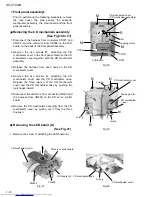
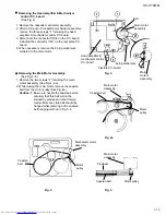
Prior to performing the following procedure, remove
the rear cover and the side panels.
Disconnect the card wires from connector CN304
and CN305 on the main board on the left side of the
body.
Disconnect the harness from connector CN309 on
the Opt, Dig.out board on the right side of the body.
Cut off the band fixing the harness.
Remove the two screws C attaching the cassette
mechanism assembly on both sides of the body and
release the two joints a.
Remove the cassette mechanism assembly in the
direction of the arrow.
1.
2.
3.
4.
Removing the cassette mechanism
assembly (See Fig.5 and 6)
Prior to performing the following procedure, remove
the rear cover, the side panels and the cassette
mechanism assembly.
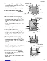
Disconnect the card wire from connector CN303 and
the harness from CN306 and CN307 on the main
board respectively.
Disconnect the harness from connector CN902 on
the power transformer.
Remove the screw E attaching the main board on
the right side of the body.
Remove the screw F and the two screws G
attaching the heat sink on the back of the body.
1.
2.
3.
4.
Disconnect connector CN301 and CN302 on the
main board from the main body. Remove the main
board upward by releasing the two joints b in the
lower part of the main board.
5.
Removing the main board / the heat sink
(See Fig.7 to 9)
The heat sink can be removed even if
the main board is attached to the body.
ATTENTION:
Fig.5
Fig.6
Fig.7
Fig.8
C
C
CN304
CN305
Joint a
Main board
Cassette mechanism assembly
Cassette mechanism assembly
CN309
Opt, Dig.out board
Band
Joint a
CN303
CN307
CN306
Transformer board
CN902
Main board
Heat sink
Joint b
Main board
CN302
CN301
Joint b
E
Summary of Contents for UX-V10GN
Page 32: ...1 32 UX V10GN LC75342 ...


