1-13
UX-V30
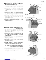
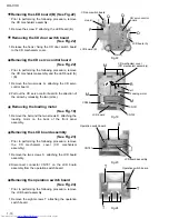
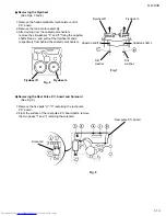
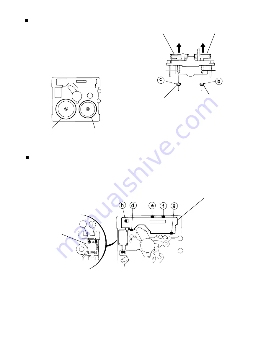
Removing the Flywheel
(See Figs. 7 and 8)
1. Remove the head amplifier & mechanism control
P.C. board.
2. Remove the main motor assembly.
3. After turning over the cassette mechanism,
remove the slit washers "b" and "c" fixing the capstan
shafts R and L, and pull out the flywheel R and L
respectively from behind the cassette mechanism.
Removing the Reel Pulse P.C. board and Solenoid
(See Fig. 9)
1. Remove the five pails "d"~"h" reataining the reel pulse
P.C. board.
2. From the surface of the reel pulse P.C. board parts, remove
the two pawls "i" and "j" retaining the solenoid.
Flywheel R
Flywheel L
Capstan shaft R
Capstan shaft L
Slit
washer
Slit
washer
Fig. 8
Flywheel R
Flywheel L
Fig. 9
Reel pulse P.C. board
Solenoid
Fig.7
j
Summary of Contents for UX-V30
Page 31: ...1 31 UX V30 LC75342 ...
Page 34: ...1 34 UX V30 MEMO ...
Page 35: ...2 1 UX V30 I H A B C D E F G 1 2 3 4 5 6 Block diagram ...
Page 39: ...2 5 UX V30 I H A B C D E F G 1 2 3 4 5 6 Tuner circuit UX V30 FM TUNER MAIN SIGNAL AM SIGNAL ...
Page 42: ...2 8 I H A B C D E F G 1 2 3 4 5 6 UX V30 UX V30 Printed circuit boards Main board ...
Page 43: ...2 9 UX V30 I H A B C D E F G 1 2 3 4 5 6 Micon P C board ...
Page 44: ...2 10 I H A B C D E F G 1 2 3 4 5 6 UX V30 UX V30 CD board ...
Page 45: ...2 11 UX V30 I H A B C D E F G 1 2 3 4 5 6 Tuner P W B ...
Page 46: ...2 12 I H A B C D E F G 1 2 3 4 5 6 UX V30 UX V30 MEMO ...
Page 48: ...UX V30 3 2 MEMO ...


