background image

30

Specifications

Englis

h

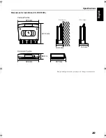
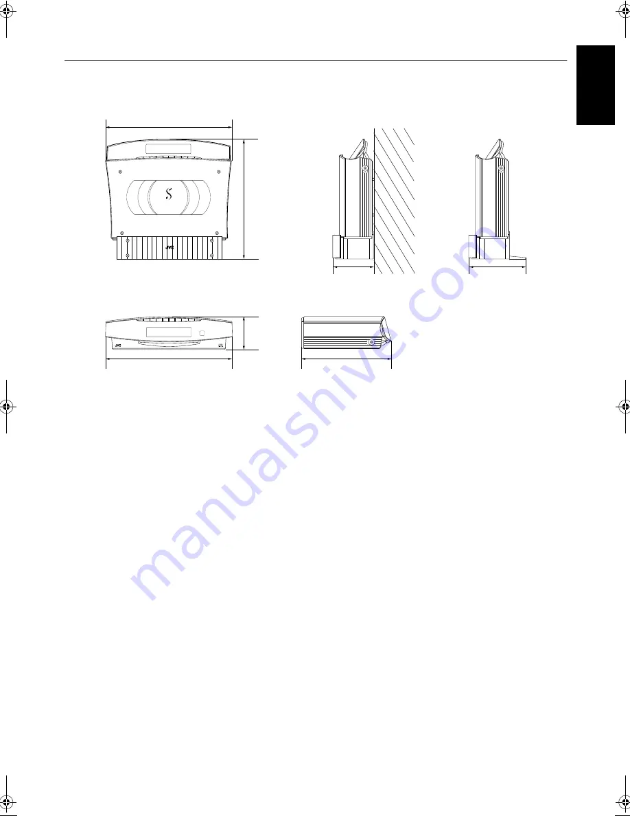
Dimensions for Installation (CA-VSDT2000)

Design and specifications are subject to change without notice.

COMPACT COMPONENT SYSTEM

PHONES

PHONES

C O M P A C T   C O M P O N E N T   S Y S T E M

PHONES

325 mm

325 mm

237 mm

301.5 mm

140 mm

86 mm

105.5 mm

Vertical Position

Horizontal Position

(On the wall)

(With Legs)

VS-DT2000[US-UW]_EN.book  Page 30  Friday, March 8, 2002  3:09 PM

Summary of Contents for VS-DT2000

Page 1: ...TOS SISTEMA DE COMPONENTES COMPACTOS For Customer Use Enter below the Model No and Serial No which are located either on the rear bot tom or side of the cabinet Retain this information for future reference Model No Serial No INSTRUCTIONS MANUAL DE INSTRUCCIONES INSTRUÇÕES LVT0854 004A US UW VS DT2000 Consists of CA VSDT2000 SP VSDT2000 and SP PW2000 Consiste de CA VSDT2000 SP VSDT2000 y SP PW2000 ...

Page 2: ...000 拨下电源插头来完全切断电源 熄灭 开关位于任何位置均不能切断电源 当本机处于待机状态时 将点亮呈红色 当本机打开时 操作指示灯将点亮呈红色 电源可以遥控操作 Cauation POWER switch SP PW2000 This apparatus is provided with a POWER switch to be able to minimize power consumption for safe use Therefore 1 When doing initial setting complete all the connections required connect the mains plug into the wall outlet and set the POWER switch to ON 2 When not in use set the POWER ...

Page 3: ...y radiación láser invisible Evite el contacto directo con el haz 3 PRECAUCIÓN No abra la tapa superior En el interior de la unidad no existen piezas reparables por el usuario deje todo servicio técnico en manos de personal calificado 1 PRODUTO LASER CLASSE 1 2 CUIDADO O laser emite uma rediação invisível que é perigosa caso o aparelho esteja aberto e a trava inoper ante ou danificada Evite exposiç...

Page 4: ...superficie nivelada Mantenga un espacio adecuado para permitir el paso del aire y una correcta ventilación situando el equipo sobre un soporte de 10 o más cm de allura Precaução Ventilação adequada Para evitar riscos de choques elétricos e incêndios e prevenir avarias instale o aparelho como segue 1 Parte tampa Sem obstruções e espaços abertos 2 Partes laterais frontal posterior Nenhuma obstrução ...

Page 5: ...be able to get out 2 Do not place any naked flame sources such as lighted candles on the apparatus 3 When discarding batteries environmental problems must be con sidered and local rules or laws governing the disposal of these bat teries must be followed strictly 4 Do not expose this apparatus to rain moisture dripping or splash ing and that no objects filled with liquids such as vases shall be pla...

Page 6: ...g conditions How This Manual Is Organized Basic information that is the same for many different functions e g setting the volume is given in the section Basic Operations and not repeated under each function The names of buttons controls and display messages are written in all capital letters e g FM AM CD NO DISC System functions are written with an initial capital letter only e g Normal Play Use t...

Page 7: ...l 12 COMPU Play 12 Basic Operations 13 Turning the Power On and Off 13 Adjusting the Brightness DIMMER 13 Changing the Color COLOR 14 Adjusting the Volume 14 Tone Control BASS TREBLE 14 Showing the Time DISPLAY 14 Using the Powered Subwoofer 15 Operating the Powered Subwoofer 15 Using the Tuner 17 Tuning In a Station 17 Presetting Stations 18 To Change the FM Reception Mode 18 Using the CD Player ...

Page 8: ... in the System Set the correct voltage for your area with the VOLTAGE SELECTOR switch on the back of the Unit By using a screwdriver slide the VOLTAGE SELECTOR switch so that it corresponds to the voltage of your area How To Put Batteries In the Remote Control Match the polarity and on the batteries with the and markings in the battery compartment CAUTION Handle batteries properly To avoid battery...

Page 9: ...nel of the Center Unit CA VSDT2000 Using the Supplied Wire Antenna Using the Coaxial Type Connector Not Supplied A 75 Ω antenna with coaxial type connector IEC or DIN45 325 should be connected to the FM 75 Ω COAXIAL termi nal If reception is poor connect the outdoor antenna Before attaching a 75 Ω coaxial lead the kind with a round wire going to an outdoor antenna disconnect the supplied FM Wire A...

Page 10: ...rd This could cause poor reception If reception is poor connect an outdoor single vinyl covered wire to the AM EXT terminal Keep the AM loop antenna connected ANTENNA OUT IN SPEAKERS AC IN AM EXT FM 75 COAXIAL AM LOOP R L MD AUX SUB WOOFER CD DIGITAL OUT SPEAKER IMPEDANCE 4 16 Attach the AM loop to its base by snapping the tabs on the loop into the slot in the base AM loop antenna Supplied AM EXT ...

Page 11: ...ame you can put either one to the right or left side Do not connect other speakers to the Unit The difference of the load impedance causes failures Do not use the supplied speakers in parallel with other speakers CAUTION A TV may display irregular colors if located near the speakers If this happens set the speak ers away from the TV Take care not to short circuit the wire leads for the speakers as...

Page 12: ... Connecting External Equipment Connect signal cords not supplied between the System s MD AUX OUT IN terminals and the output input terminals of the external MD recorder tape deck etc You can then listen to the external source through the System or record the System s CD player or tuner to the external unit Spacer supplied Bottom of the powered subwoofer SUB WOOFER Powered Subwoofer Signal cord sup...

Page 13: ... THE JVC POWER CORD PROVIDED WITH THIS SYSTEM TO AVOID MALFUNCTION OR DAMAGE TO THE SYSTEM BE SURE TO UNPLUG THE POWER CORD FROM THE OUTLET WHEN GOING OUT OR WHEN THE SYSTEM IS NOT IN USE FOR AN EXTENDED PERIOD OF TIME Installing the Unit on the Stand You can place the Unit vertically by attaching the supplied Stand Avoid an unstable place when placing the Unit vertically Select a place on the lev...

Page 14: ...ews makes for an unstable attachment and causes a safety hazard as the Center Unit may fall down Location of attachment to a wall Care is required in selecting a location for attaching the Center Unit to the wall Injury to personnel or damage to the Center Unit may result if the Center Unit is attached in a location which interferes with daily activities or a location that the users are liable to ...

Page 15: ...balance causing the Center Unit to fall Make sure that the cords will not interfere with daily activities and that the users will not trip over them Do not pull the con nected cords with excessive force Check regularly that none of the screws are loose In the event that the Center Unit has fallen turn off the power disconnect its power plug from the power outlet and contact your dealer for an insp...

Page 16: ... into the wall outlet and your System is at your command Before operating verify that the display shows the clock If malfunctions may occur re connect the power cord When the Unit is placed vertically Set the DISP SET switch to V When the Unit is placed horizontally Set the DISP SET switch to H SPEAKER IMPEDANCE 4 16 R L SPEAKERS OUT IN MD AUX CD DIGITAL OUT SUB WOOFER ANTENNA FM 75 COAXIAL AM EXT...

Page 17: ...s of the play button for that function One Touch Operation turns the power on for you then starts the function you have specified If the System is not ready no CD in place the System still powers on so you can insert a CD How One Touch Operation works in each case is explained in the section dealing with that function The COMPU PLAY buttons are On the Remote Control 3 8 button FM AM button MD AUX ...

Page 18: ...e reset to 0 00 after about 20 minutes Adjusting the Brightness DIMMER Using the Remote Control You can adjust the brightness of the backlighting for the dis play and the illumination on the cover When the System is Turned On Each time you press the DIMMER button on the Remote Control the brightness of the backlighting and the illumina tion on the cover change as follows When the System is turned ...

Page 19: ...urn down the volume be fore connecting or putting on head phones Tone Control BASS TREBLE Using the Remote Control You can control the tone by changing the bass and treble BASS Control You can adjust the bass level low frequency range level between 5 and 5 0 Flat 1 Press the BASS button on the Remote Control 2 Press the or button on the Remote Control to adjust the bass level TREBLE Control You ca...

Page 20: ...chness more to the bass press the PHASE button to set it either in the _ REVERSE position or the NORMAL position whichever can add the rich ness to the bass Normally the PHASE button should be set in the NOR MAL position Automatic Operating Status On Off To save energy the Subwoofer enters the Standby mode if no or very weak sound signals come into the Subwoofer for about 5 minutes In Standby mode...

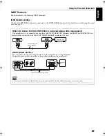
Page 21: ...does not have the SUB WOOFER OUT terminals the RIGHT and LEFT MONO ter minals will be connected to the LINE OUT RIGHT and LEFT terminals of that unit INPUT HIGH LEVEL You can connect the speaker output terminals of other amplifier etc to these terminals Connect the speaker cords in parallel to the speaker terminals on the amplifier etc Do not use the INPUT LOW LEVEL terminals and the INPUT HIGH LE...

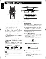
Page 22: ...h Radio Just press the FM AM button on the Remote Control to turn on the System and start playing the station you were last tuned to You can switch from any other sound source to the radio by pressing the FM AM button on the Remote Control or the SOURCE button on the Unit Tuning In a Station 1 Press the FM AM button The Band and Frequency you were last tuned to appear on the display If the last st...

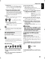
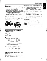
Page 23: ...utton SET will blink for 5 seconds Within 5 seconds proceed to the next step When the display returns to the one set in step 2 after 5 seconds press the SET button again 4 Press the or button within 5 seconds to select the preset number or button Increase or decrease the preset number by 1 Pressing and holding the button will rapidly increase or decrease the preset number 5 Press the SET button wi...

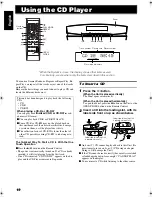
Page 24: ...D 1 Press the button When the Unit is placed vertically The Panel opens automatically When the Unit is placed horizontally To open the Panel press the 0 button on the Unit or the OPEN CLOSE button on the Remote Control 2 Insert a CD into the loading slot with its label side front or up as shown below An 8 cm 3 CD cannot be played back in this Unit Do not attempt to insert an 8 cm 3 CD using an ada...

Page 25: ...isplay To cancel pause press the same button again Play con tinues from the point where it was paused To Select a Track or Passage within a Track In the stop mode or during playback press the Number but ton on the Remote Control to select the track you want The selected track starts playing For the track number more than 10 press the 10 button then the Number button OR During playback press the 4 ...

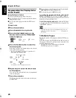
Page 26: ...ays the tracks in the order you have pro grammed them You can skip to a particular program track by pressing the 4 or button during Program Play To stop playing press the 7 button once To confirm the programmed tracks while the CD player is stopped each time press the 4 or but ton the tracks making up the program will successively be displayed in the programmed order To exit the program mode once ...

Page 27: ... or individual track as many times as you like Press the REPEAT button on the Remote Control The Repeat indicator changes with each press of the button as shown below ALL blank display back to the beginning Repeats one track ALL In Normal Play mode repeats all the tracks In Program Play mode repeats all the tracks in the program In Random Play mode repeats all the tracks in random order To exit Re...

Page 28: ... System s source to external equipment which is connected to the MD AUX IN OUT or CD DIGI TAL OUT terminals of the System such as cassette deck or MD recorder etc First make sure that the external equipment is properly connected to the System See page 7 1 Play the System s CD Player or tune in to a station The recording level is not affected by the VOLUME level set by the System Also it is not aff...

Page 29: ...The minute digits of the time indication rapidly blink on the display 5 Press the or 4 button to set the minute 6 Press the SET button The selected time is set and the seconds start counting from 0 CAUTION If there is a power failure the clock loses its setting after about 20 minutes 0 00 blinks on the display and the clock must be reset The clock may gain or lose one to two minutes per month The ...

Page 30: ... want the Unit to come on using the or 4 button 2 Setting the OFF time Example 13 30 1 Press the SET button The hour digit of the OFF time blinks on the display The same time as the ON time will be automatically set Set the hour you want the Unit to be turned off using the or 4 button 2 Press the SET button The minute digits of the OFF time blink on the dis play Set the minute you want the Unit to...

Page 31: ...en it is playing By setting the Sleep Timer you can fall asleep to music and know that your Sys tem will turn off by itself rather than play all night You can only set the Sleep Timer when the System is on and a source is playing 1 Play a CD or tune in to the desired sta tion 2 Press the SLEEP button on the Remote Control The SLEEP indicator lights up When the clock is not set 0 00 appears on the ...

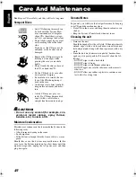
Page 32: ...nt and wrung well then wipe clean with a dry cloth Since the unit may deteriorate in quality become dam aged or get its paint peeled off be careful about the fol lowings DO NOT wipe it with a hard cloth DO NOT wipe it strong DO NOT wipe it with thinner or benzine DO NOT apply any volatile substance such as insecti cides to it DO NOT allow any rubber or plastic to remain in con tact with it for a l...

Page 33: ... Control The path between the Remote Control and the sensor on the Unit is blocked The batteries have lost their charge Remove the obstruction Replace the batteries Operations are disabled The built in microprocessor has malfunctioned due to external electrical interference Unplug the System then plug it back in CD NO DISC appears There is no disc loaded Insert a disc CANNOT PLAY or UNFINALIZ appe...

Page 34: ...e 2 5 W power save mode Center Unit Dimensions 325 mm 86 mm 237 mm W H D Mass Approx 4 0 kg without Stand and Legs Speaker Specifications each unit SP VSDT2000 Speakers 9 5 cm 1 cm track type dome Impedance 4 Ω Dimensions 125 mm 317 mm 125 mm W H D Mass 560 g Powered Subwoofer SP PW2000 Speaker Woofer 16 cm 4 Ω 1 Rated Impedance 4 Ω Frequency Response 30 Hz 280 Hz Input sensitivity Impedance LOW L...

Page 35: ...0 Design and specifications are subject to change without notice COMPACT COMPONENT SYSTEM PHONES PHONES C O M P A C T C O M P O N E N T S Y S T E M PHONES 325 mm 325 mm 237 mm 301 5 mm 140 mm 86 mm 105 5 mm Vertical Position Horizontal Position On the wall With Legs ...

Page 36: ...e outside of this equipment and if different reset the voltage selector switch to prevent from a damage or risk of fire electric shock IMPORTANTE para la línea de la red CA ANTES DE ENCHUFAR EL EQUIPO compruebe si la tensión de la línea de la red CA corresponde con la posición del selector de tensión situado en la parte exterior del equipo y si es diferente reajuste el selector de tensión para evi...

Reviews: