


SERVICE MANUAL
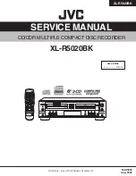
CD/CDR MULTIPLE COMPACT DISC RECORDER
No.A0035
Aug. 2002
COPYRIGHT 2002 VICTOR COMPANY OF JAPAN, LTD.
XL-R5020BK
XL-R5020BK
Area Suffix
J ------------- U.S.A.
XLÐR5020 CD/CDR MULTIPLE COMPACT DISC RECORDER
MP3 PLAYBACK
COMPACT
DIGITAL AUDIO
Recordable
ReWritable
MIN
MAX
COMPACT
DIGITAL AUDIO
CA
NC
EL
R
EC
SO
UR
CE
DI
SP
LA
Y
ME
NU
1
CD1
CD2
CD3
STANDBY/ON
PLAY
CD REC
CD EDIT SYNCHRO
FADE
REC
RM-SXL001J
REMOTE CONTROL
PITCH 0
PITCH
FINALIZE
REC MUTING
MODE
SET
GROUP
REPEAT
CD
CDR
4
7
10
2
5
8
3
6
9
10
GROUP
CONTROL
GROUP


