


For Customer Use:
Enter below the Model No. and Serial
No. which are located either on the rear,
bottom or side of the cabinet. Retain this
information for future reference.
Model No.
Serial No.
LVT0728-002A
[C]
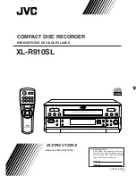
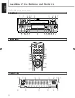
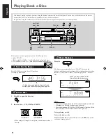
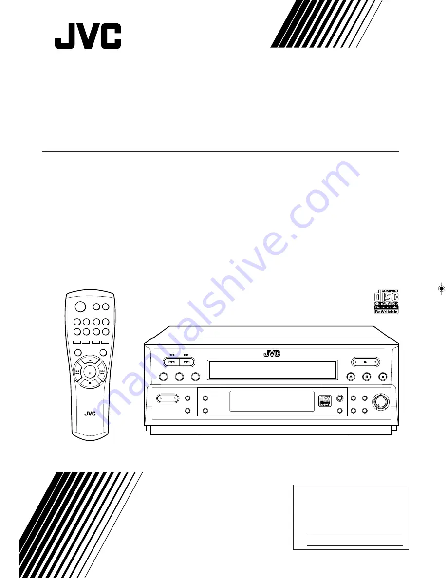
XL-R910SL
COM P ACT DIS C R ECOR DER
P R OGR AM
S ET
CLEAR
R EP EAT
_
ON /
Ñ
OFF
P OW ER
R AN DOM
AUTO
TR ACK
DIS P LAY
R EC
P AUS E
R EC
R EC LEVEL
M IN
M AX
FIN ALIZE
ER AS E
R EC
S OUR CE
DIGITAL
S YN CHR O
X L -R 9 1 0
OP E N / C LOS E
R M -S X LR 9 1 0 A
R E M OTE C ON TR OL
R E C
P A U S E
R E C
S OUR C E
R E C
R AN DOM
DIS P LAY
P LAY
S TOP
P AUS E
R E P E AT
1
3
4
5
6
7
8
9
0
2
0
INSTRUCTIONS
MANUAL DÕINSTRUCTIONS
COMPACT DISC RECORDER
ENREGISTREUR DE DISQUES LASER
XL-R910[C]_COVER_f
01.3.13, 5:40 PM
1