XM-R700SL
1-10
1.
2.
3.
Attach the magnetic head assembly by cramping
the MD mechanism assembly. Then, fix the
magnetic head assembly to the pickup assembly
on the underside of the chassis assembly by
tightening the two B screws.
Attach the left edge of the head protector and the
right edge.
Connect the magnetic head flexible harness to the
connector on the magnetic head board.
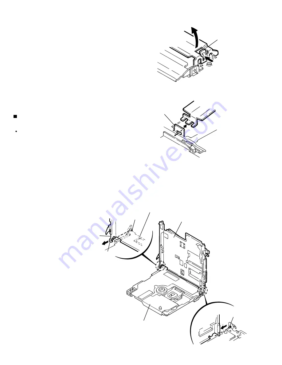
Removing the Holder assembly
(See Fig.3 and 6)
1.
2.
3.
Prior to performing the following procedure,
remove the magnetic head assembly.
Remove the screw C of the chassis assembly part
c and lift the edge of the holder assembly in the
direction of the arrow d (See Fig.3).
Move the part e of the holder assembly in the
direction of the arrow to release the U-shaped
notch from the shaft.
Pull the part f of the holder assembly in the
direction of the arrow to release it from the shaft.
CAUTION: When reassembling the magnetic head
assembly, reverse the order of the
removing procedure.
Fig. 4
Fig. 5
Fig. 6
Push
Convex part (b)
Lift up
Right side of the
head protector
Left side of the
head protector
Slit
Pull
Chassis assembly
Holder
assembly
Shaft
Part f
Part e
Chassis assembly
U-shaped notch
Holder assembly
Shaft
Chassis assembly
Holder assembly
Summary of Contents for XM-R700SL
Page 40: ...2 2 XM R700SL M E M O ...
Page 46: ...XM R700SL 3 2 M E M O ...


