XV-LTR1
1-8
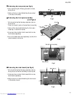
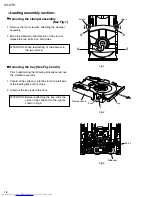
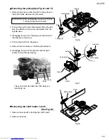
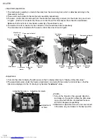
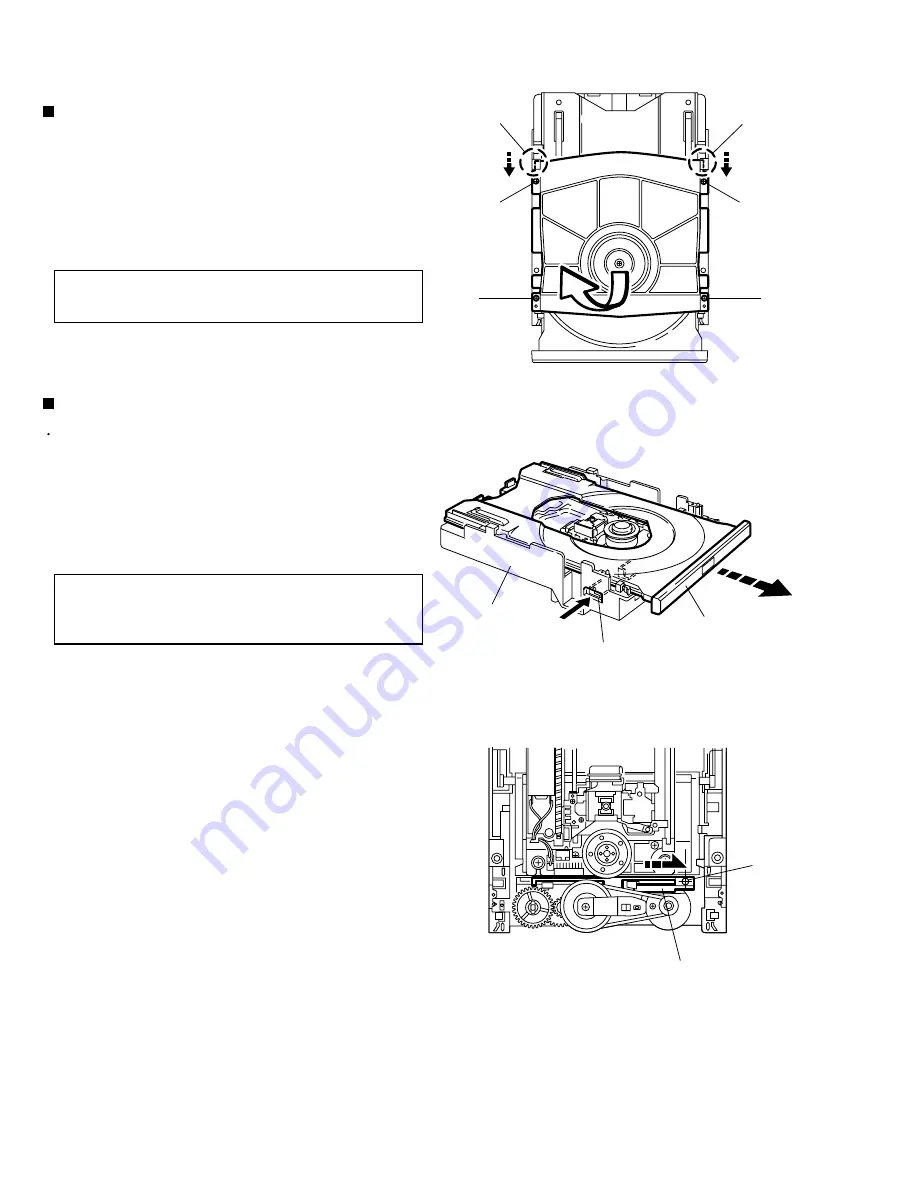
Remove the four screws
A
attaching the clamper
assembly.
Move the clamper in the direction of the arrow to
release the two joints
a
on both sides.
1.
2.
<Loading assembly section>
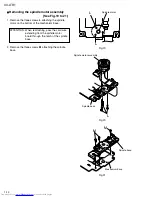
Removing the clamper assembly
(See Fig.1)
Prior to performing the following procedure, remove
the clamper assembly.
Push
b
of the slide cam into the slot on the left side
of the loading base until it stops.
Draw out the tray toward the front.
1.
2.
Removing the tray (See Fig.2 and 3)
When reattaching, fit the clamper to
the two joints
a
.
ATTENTION:
Before reattaching the tray, slide the
part
c
of the slide cam to the right as
shown in Fig.3.
ATTENTION:
Joint a
Joint a
A
A
A
A
Fig.1
Fig.2
Fig.3
Push
b
Tray
Clamper base
Part c
Slide cam


