36
JVL Industri Elektronik A/S - User Manual - Ethernet for MAC and MIS motors
3.2
Protocol specifications
3.2.1
EtherCAT® - communication
The EtherCAT® fieldbus system is standardised by the EtherCAT® user organisation
(ETG). The driving force behind this is the german company, Beckhoff GmbH. Due to
the advanced Ethernet technology used for EtherCAT®, in the future, customers can
change from other fieldbus systems to EtherCAT® or generally equip new plant models
with EtherCAT®.
Communication on EtherCAT® is based on a master/slave operation. The update cycle
between master and slave depends on the number of EtherCAT® slaves, the amount of
process data of the individual slaves, and the set update time of the master. Due to the
ring topology, in every bus cycle only one telegram is sent on the bus. The bus cycle time
thus remains exactly the same in every cycle.
Slave addressing can be done in two ways:
• Auto increment addressing
• Fixed node addressing
With Auto increment addressing the master scans the net for slaves, and the slaves are
then addressed in the sequence they are physically present on the net. With fixed node
addressing, the addresses that each node has programmed, is used.
3.2.2
EtherCAT® frame structure
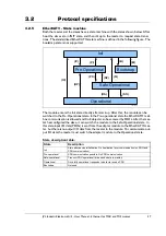
In EtherCAT®, the data between the master and the slaves is transmitted in Ethernet
frames. An EtherCAT® Ethernet frame consists of one or several EtherCAT® tele-
grams, each addressing individual devices and/or memory areas. The telegrams can be
transported either directly in the data area of the Ethernet frame or within the data sec-
tion of a UDP datagram transported via IP. The EtherCAT® frame structure is pictured
in the following figure. Each EtherCAT® telegram consists of an EtherCAT® header, the
data area and a working counter (WKC), which is incremented by all EtherCAT® nodes
that are addressed by the telegram and have exchanged associated data.
3.2.3
Sync managers
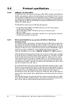
Sync managers control the access to the application memory. Each channel defines a con-
sistent area of the application memory. The adapter module has four sync manager chan-
nels. The mailbox protocol (SDO's) and process data (PDO's) are described later in this
chapter.
3.2.4
Sync manager watchdog
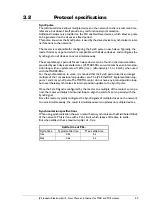
The sync manager watchdog monitors the output sync managers. If the output data is not
updated by the EtherCAT® master within the configured time, the watchdog will acti-
vate time out and change the state of the adapter module from Operational to Safe-Op-
erational.
Note: EtherCAT® has been designed so that it provides no way for a slave to monitor
the connection to the master if the slave gets no output data.
Note: The drive reaction to a communication fault must be configured in the module
write flag register (object 2011 subindex 6 - motor set passive or motor set velocity =0).
Preamble Ethernet header
8 bytes
14 bytes
Checksum
4 bytes
EtherCAT
header
1'st Datagram
header
2 bytes
10 bytes
Data
WKC
2 bytes
n'th EtherCAT datagram
-
44 - 1498 bytes
-
TT3007GB
Summary of Contents for MAC00-EC4
Page 2: ......
Page 14: ...14 JVL Industri Elektronik A S User Manual Ethernet expansion modules for MAC motors ...
Page 32: ...32 JVL Industri Elektronik A S User Manual Ethernet for MAC and MIS motors ...
Page 78: ...78 JVL Industri Elektronik A S User Manual Ethernet for MAC and MIS motors ...
Page 136: ...136 JVL Industri Elektronik A S User Manual Ethernet for MAC and MIS motors ...
Page 176: ...176 JVL Industri Elektronik A S User Manual Ethernet for MAC and MIS motors ...
Page 177: ...JVL Industri Elektronik A S User Manual Ethernet for MAC and MIS motors 177 8 Sercos ...
Page 224: ...224 JVL Industri Elektronik A S User Manual Ethernet for MAC and MIS motors ...
Page 241: ...JVL Industri Elektronik A S User Manual Ethernet for MAC and MIS motors 241 ...
Page 252: ...252 JVL Industri Elektronik A S User Manual Ethernet for MAC and MIS motors ...
Page 256: ...256 JVL Industri Elektronik A S User Manual Ethernet for MAC and MIS motors ...
Page 257: ...JVL Industri Elektronik A S User Manual Ethernet for MAC and MIS motors 257 12 Appendix ...


