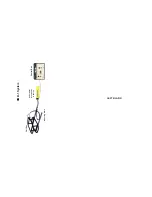
GPS OPTION (used with RS232 Control Box option)
The GPS option allows the boat's GPS to be connected to the
Control Box. This option is used with the RS232 Control Box option
which will then output the boat's GPS and the RMD's output signal
to a computer.
Attach the output cable from the GPS system to the RMD-1
Control Box.
NOTE: The GPS system must have a serial output, not USB.
There is no adaptor to connect a GPS with USB output to a serial
port.
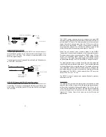
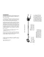
If the data cable for your GPS has a 9 pin “D” connector on the
end (for a PC serial port), it will connect directly to the “GPS
INPUT” jack on the Control Box. If the data cable for your GPS
has bare wire leads on the end, you will need to splice the
appropriate wires to the cable shown below. If your GPS did not
come with a data cable, one can be obtained from the GPS
retailer or manufacturer. There are usually a variety of cables
available, many also include connections for an external power
source for the GPS. We recommend using an external power
source as using the GPS with the data output consumes a set of
small batteries in a few hours.
INTRODUCTION
The RMD-1 is a high performance Pulse Induction metal detector
which can be attached to almost any ROV or towed underwater
system. Pulse induction technology allows the RMD-1 to detect both
ferrous and non-ferrous metal objects under the ocean floor while
ignoring mineralization in the salt water and seabed. The ROV metal
detector locates and tracks underwater pipelines, finds missing
tools and dredge parts, locates weapons and unexploded ordnance,
and finds lost treasure.
Pulse detectors have had a major impact on the salvage business.
Their major claim to fame is that they are very sensitive and do not
detect minerals (extreme concentrations of iron ore may give a
modest reading). This lack of mineral detection is an answered
prayer for salt water divers who have to contend with heavy miner-
alized deposits on the ocean floor which produce false readings on
conventional detectors. Pulse detectors ignore these mineral de-
posits and respond only to metal targets (ferrous and non-ferrous
metal).
HOW PULSE DETECTORS WORK
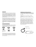
Pulse detectors operate by transmitting a continuous stream of high
energy magnetic pulses (one hundred per second), from the Coil.
After each pulse is transmitted, the unit then "listens" using the Coil
as the receiving antenna.
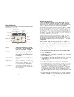
Coil
Figure 1
When a transmitted pulse hits a metal object, a magnetic field is
induced in the object. This causes eddy currents to flow in the metal,
which in turn generates a second magnetic field. This field is picked
up by the Coil, amplified, and then displayed by the meter and heard
in the speaker/earphone
.
1
PULSE
COIL
NOTE: The transmitted
pulse covers a much
larger area than shown
above.
EDDY CURRENTS
COIL
COIL
RECEIVE
target
14
Coil
Coil
Coil
GPS DATA CABLE
red wire for Signal (Data Out)
black wire for Return (Data
Ground)
To RMD-1 Control Box
SOLDER WIRES TO
GPS DATA CABLE


