


17
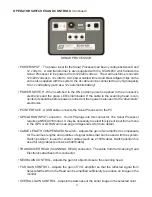
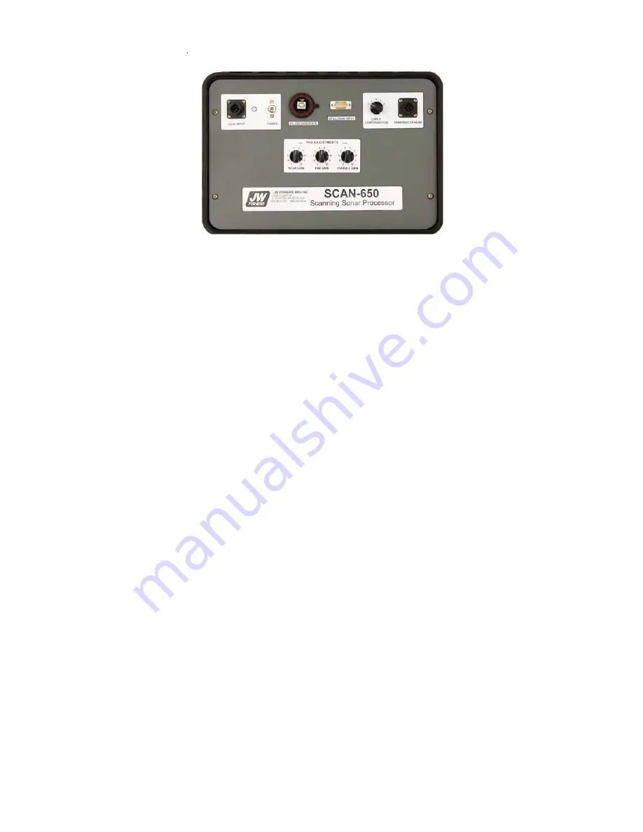
OPERATOR SWITCHES AND CONTROLS
(continued)
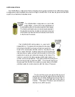
• POWER INPUT - The power input for the Sonar Processor can be any voltage between 9 and
12 volts dc. A wall transformer is also supplied with the SCAN-650 which allows the
Sonar Processor to be powered from 120/220 volts ac. The wall transformer converts
120/220 volts ac to 12 volts dc. A dc power cable with red and black alligator clips on the
end is also supplied with the system; the dc cable can be connected to any high capacity
9 to 12 volt battery (such as a 12v automobile battery).
• POWER SWITCH - When switched to the ON position power is applied to the processor’s
electronics and the green LED is illuminated. If the cable to the scanning head is con-
nected (it should be before power is turned on) then power is also sent to the “downstairs”
electronics.
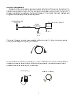
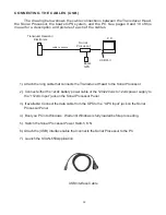
• PC INTERFACE - A USB cable connects the Sonar Processor to the PC
• GPS/LORAN INPUT connector - Your GPS plugs into this connector. The Sonar Processor
requires a NMEA 0183 input. It may be necessary to select this type of input from a menu
in the GPS or LORAN unit (see page 34 Appendix A for more detail).
• CABLE LENGTH COMPENSATION switch – Adjusts the gain of an amplifier to compensate
for the various lengths and qualities of signal cables that can be used with the system.
Switch position 1 is used for shorter cables (such as a 150ft cable). Switch position 5 is
used for long cables (such as a 2000ft cable).
• TRANSDUCER HEAD (SCANNING HEAD) connector - The cable from the Scanning Head
Electronics attaches to this connector.
• NEAR GAIN CONTROL - Adjusts the gain for objects close to the scanning head.
• FAR GAIN CONTROL - Adjusts the gain of TVG amplifier so that the reflected signal from
objects farthest from the Head can be amplified sufficiently to produce an image on the
monitor.
• OVERALL GAIN CONTROL - Adjusts the darkness of the sonar image in the selected color.
SONAR PROCESSOR
Summary of Contents for SCAN-650
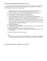
Page 10: ...10 LEFT BLANK...


