34
Step 3.
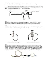
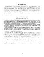
If the data cable for your GPS has a 9 pin “D” connector on the end (for a PC serial port), then you can
connect the GPS directly to the GPS INPUT jack on the Sonar Processor panel. If the data cable for
your GPS has bare wire leads on the end, you will need to splice the appropriate wires to the cable
(shown below). If your GPS did not come with a data cable, one can be obtained from the GPS retailer
or manufacturer. There are usually a variety of cables available, many also include connections for an
external power source for the GPS. We recommend using an external power source as using the GPS
with the data output consumes a set of small batteries in a few hours.
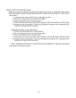
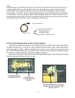
ATTACH THE SCANNING HEAD TO ROV OR POLE HANDLE
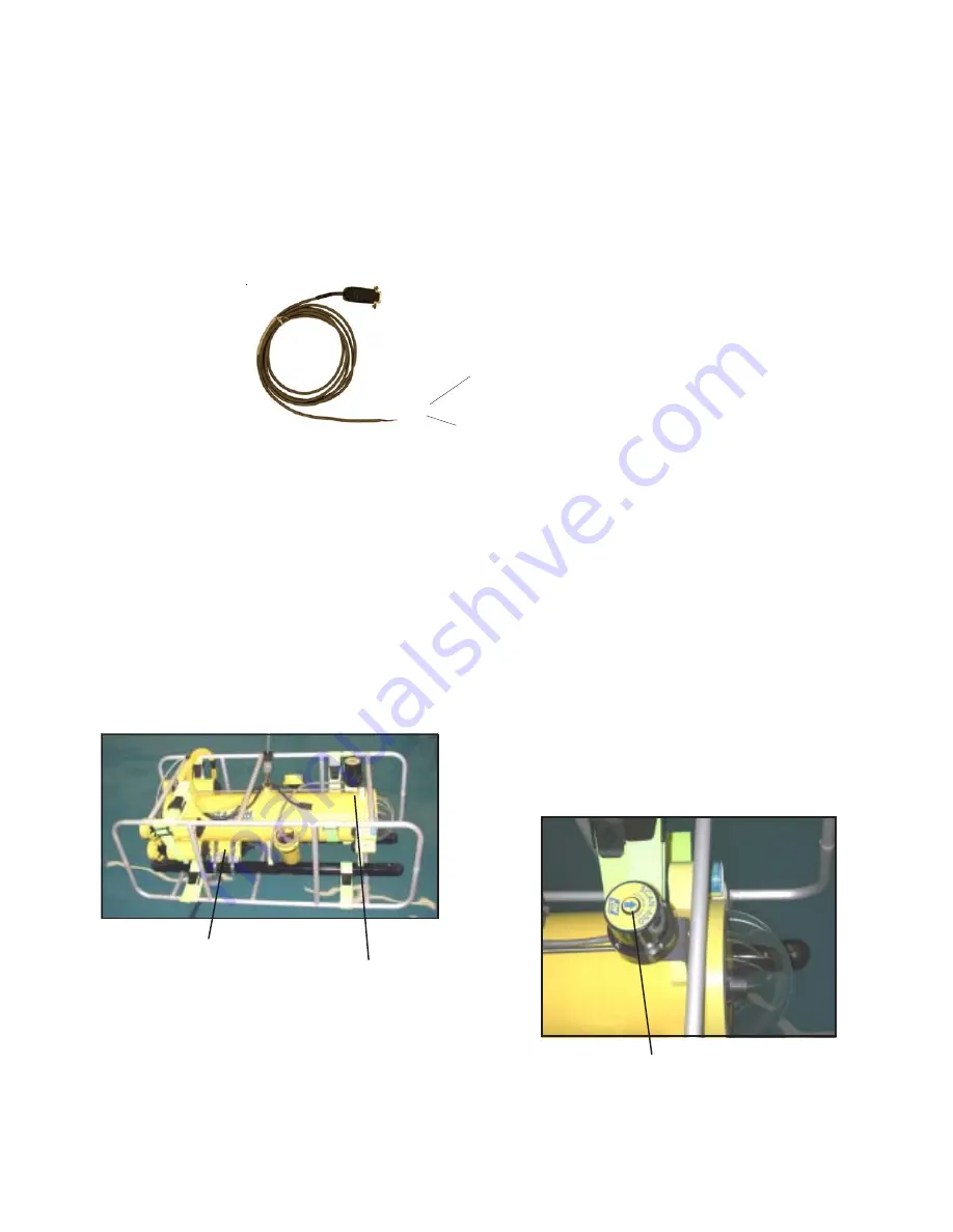
After attaching the SCAN-650 cables to the appropriate system components, the Scanning Head can
be attached to the ROV or mounted on a pole handle for operation from a boat. When attaching the
Scanning Head to an ROV, if the Head and Electronics are in one unit, mount the unit on the top of the
ROV. If the Head and Electronics are separate units, mount the head on the top of the ROV and the
Electronics in a protected position on the side, or bottom, of the ROV.
Note: Be sure the arrow on top of the Scanning Head is pointing forward. The arrow points to the area
that will be displayed at the top of the PC screen.
red wire for Signal (Data Out)
black wire for Return (Data Ground)
To Sonar Processor
SOLDER WIRES TO
GPS DATA CABLE
Mount Scanning Head arrow facing
forward, this will be the top of the
display on the PC
Scanning electronics
strapped to ROV skid
Scanning Head
mounted uptop and
forward
Summary of Contents for SCAN-650
Page 10: ...10 LEFT BLANK...