background image

42

Problem:

“A Required Interface Board Was Not Found” message

JW Fishers Sonar systems use an interface board to capture the analog sonar signal and

convert it to digital data which the software can then process.  The driver software for this interface
board is installed as part of the JW Fishers Sonar application installation process.  After the JW
Fishers Sonar application installation process is completed and before the sonar system is run for
the first time, a program to configure the interface board must be run.  This program must also be
run whenever the Sonar Processor is used with a different PC.
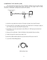
USB Systems:

The SP to PC Interface (USB) Cable must be connected to the Sonar Processor and PC

1. From the Start menu select Programs / Measurement Computing / InstaCal.
2. The InstaCal software starts.
3. A ‘Plug and Play Board Detection’ window should open.  USB-1208HS should show in the

window.  Click ‘OK’

4. ‘Board #0 - USB-1208HS’ should show in the board list window.
5. From the ‘Install’ pull-down menu click on ‘Configure’. The ‘Board Configuration’ box opens.
6. Next to ‘Number of Channels’, select ‘8 Single Ended’. From the drop down list.
7. Click ‘OK’ to continue.
8. Exit the InstaCal program.

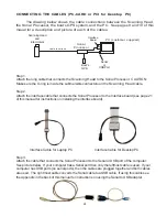
PC-CARD (older) systems

The PC-CARD Interface Board must be Installed in the PC

1. From the Start menu select Programs / Measurement Computing / InstaCal.
2. The InstaCal software starts.
3. In the ‘PC Board list’ click on ‘PC-CARD-DAS16/330’ to highlight it.
4. From the ‘Install’ pull-down menu click on ‘Configure’. The ‘Board Configuration’ box opens.

• Next to ‘Clock 0 Source’, select ‘Internal’.
• Next to ‘Clock Speed’, select ‘10MHz’.
• Next to ‘ADC External Pacer Edge’, select ‘Rising’.
• Click ‘OK’ to continue.

5. From the ‘Calibrate’ pull-down menu click on ‘A/D’. The automatic calibration will begin.

Allow the calibration to complete. When calibration is complete, click ‘OK’.

6. Exit the InstaCal program.

The interface board is now configured.

Troubleshooting (continued)

Summary of Contents for SCAN-650

Page 1: ...50 Scanning Sonar OPERATION MANUAL JW FISHERS MFG INC rev 811 JW FISHERS MFG INC 1953 COUNTY ST E TAUNTON MA 02718 USA 508 822 7330 800 822 4744 FAX 508 880 8949 Email jwfishers aol com WEB www jwfish...

Page 2: ...Sonar OPERATION AND MAINTENANCE MANUAL JW FISHERS MFG INC 1953 COUNTY ST E TAUNTON MA 02718 USA 508 822 7330 800 822 4744 FAX 508 880 8949 Email jwfishers aol com WEB www jwfishers com Surface Sonar...

Page 3: ...ONENTS 9 THEORY OF OPERATION 11 OPERATOR SWITCHES AND CONTROLS 16 INSTALLING HARDWARE AND SOFTWARE 27 CABLING THE SYSTEM 31 ATTACHING TO ROV 32 OPERATION 35 SAMPLE PLAYBACK 36 SAMPLE RECORDING 37 FAQs...

Page 4: ...head The black flexible boot is an acoustic window that should be keep clean soap and water and protected from damage Do not remove the 6 screws that hold the black flexible boot in place on the scan...

Page 5: ...rom Sonar Processor or 9 36 from ROV Cable 2 or 4 conductor DIMENSIONS WEIGHT Sonar Processor 8 Wx9 Dx2 5 H 2 lbs 0 9 Kg 650A Scanning Head and housing 3 5 Dia x 10 5 L 3 6 lbs 1 6 Kg air 0 lbs 0 Kg w...

Page 6: ...52 meg hr 13 hrs CD 90 hrs DVD 2 deg step 30 meg hr 23 hrs CD 200 hrs DVD 10 Meter Range 5 deg step 27 meg hr 25 hrs CD 170 hrs DVD 2 deg step 17 meg hr 39 hrs CD 270 hrs DVD 60 Meter Range 5 deg step...

Page 7: ...e black scanning head is connected permanently to the electronics module A cable not shown comes out of the bottom of the electronics module and connects to the Sonar Processor The SCAN 650B configura...

Page 8: ...see Settings Menu pg 18 The target below is a pickup truck note large black shadow located in 18 feet of water The scanning head was mounted on a pole which was deployed from a small boat see top pho...

Page 9: ...able to surface Sonar Processor 12345 12345 12345 12345 PC customer supplied Boat s GPS USB Port The Sonar Processor can be powered by 9 12 vdc A 120 220 vac to 12 vdc wall transformer is supplied to...

Page 10: ...10 LEFT BLANK...

Page 11: ...nverts the vibration into an electrical signal This signal is then detected and ampli fied by the receiver The control display unit regulates the precise timing between the transmitters receiver and d...

Page 12: ...h When the bottom slopes away and down from the fish only light echo s return from the bottom When the bottom slopes upward medium echo returns are received If a hard target is positioned on a down or...

Page 13: ...re 720 steps for 1 2 degree AfterthereturnsignalsareprocessedbytheTVG theSonarProcessortakesevenlyspaced samples of the echo returns which are processed and displayed on the PC screen as a very narrow...

Page 14: ...ig 4 TIME VARIABLE GAIN TVG TheSonarProcessorcontainsaTVGcircuitonthePCboardthatreceivestheechosignalsfromthe fishpreamplifierboards TheTVGcircuitamplifiesandmakestimevariablegainadjustmentstothe sign...

Page 15: ...the bottom Near Gain Adjusts the TVG gain at the start of the sweep objects close to the scanning head Far Gain Adjusts the TVG gain at the finish objects furthest from the scanning head Operator adj...

Page 16: ...display There is also communications fromthecomputertothetransdcucer whichallow theoperatortocontroldifferentfunctionswithinthe Fish Sonar Processor The Sonar Processor amplifies and conditions the si...

Page 17: ...the Sonar Processor to the PC GPS LORAN INPUT connector Your GPS plugs into this connector The Sonar Processor requires a NMEA 0183 input It may be necessary to select this type of input from a menu i...

Page 18: ...ions available under each heading File Record new file This is used to record a new sonar file Open file Use this to open an existing sonar file for playback Save screen as a picture Saves the image o...

Page 19: ...ger viewing area Center Left Right Top Bottom can be selected Show Range Rings Makes the range rings visible in the sector the sonar is sweeping This can assist the operator in determining the distanc...

Page 20: ...inverted as if it was pole mounted and deployed over the side of a boat If the orientation is set incorrectly targets that should be displayed on the left side of the screen will be displayed on the r...

Page 21: ...er Zooms in on sonar image Mode Screen Toolbar The Mode Screen toolbar allows for easy 1 click access to many software functions A Tooltip stating the name of a button will appear when the mouse curso...

Page 22: ...ed move the slider toward FAST until the data is only shown in half of the screen sector a mirror image is shown in each half of the chosen sector Now move the slider slightly toward SLOW until data i...

Page 23: ...ssing the and keys on the keyboard Color Bar Displays the colors for the sonar image being displayed Zero or weak echo returns are represented by the colors on the left side of the bar and strong retu...

Page 24: ...12 hr or 24 hr clock can be selected Date Shows today s date gets info from computer Under Settings top toolbar Month Day Year or Day Month Year can be selected Size Allows the operator to measure th...

Page 25: ...anges magnifying the sonar image to a maximum of 200 Start of Sweep End of Sweep Allows the user to select the sector that will be scanned The angle can be selected from the pulldown menus or can be t...

Page 26: ...f the target 5 Release the left mouse button The size of the target in meters will be displayed in the window to the right of the Size button Alternately the Size can be measured by 1 Press and hold t...

Page 27: ...er box does not open within 60 seconds the installation can be performed from Windows Explorer A Open Windows Explorer from the Start Programs menu B Select Jwf SCAN 650 Click on Setup exe This will s...

Page 28: ...50 software installation will complete Click Close in the Installation Complete box 13 A messagebox will appear stating You must restart your computer for the con figuration changes made by JW Fishers...

Page 29: ...eady been installed on the PC It is not necessary to insert the CD Select Install the software automatically Recommended then click Next to continue InstaCal program Interface board configuration and...

Page 30: ...the SCAN 650 can be used for the first time this program must be run to configure and calibrate the Interface board This program will also need to be run if the Interface board has been removed and re...

Page 31: ...ected to the PC with a USB Cable 6 After clicking on Ports Com LPT one or more items will be shown Look for the item that refers to your USB to Serial Adapter it will be something like Prolific USB to...

Page 32: ...12vdc battery power cable or the 120 220 vac to 12vdc power supply to the 12vdc Input jack on the Sonar Processor Panel 3 If available Connect the data cable from the GPS to the GPS Input jack on the...

Page 33: ...USB port of the computer See picture below If your computer has a Serial port then only the leftmost cable is used If your computer has USB ports no serial ports then the cables are plugged together a...

Page 34: ...R POLE HANDLE After attaching the SCAN 650 cables to the appropriate system components the Scanning Head can be attached to the ROV or mounted on a pole handle for operation from a boat When attaching...

Page 35: ...nge step de grees sector zoom etc See Operator Switches and Controls and sample Recording section of this manual for a complete description of each of these functions 7 Choose the proper selections in...

Page 36: ...lue arrowhead with the line in front is the Rewind to beginning of file button Using the Rewind button the operator can rewind the file being played to any point on the recorded file Click the Stop bu...

Page 37: ...ing setting When an image of interest is appears on the screen the operator can select one of the other zoom settings 150 or 200 to enlarge the image The operator can also choose which portion of the...

Page 38: ...Gain The Near Gain usually requires little or no adjustment e Adjust the Overall Gain so that only the very strongest returns from hard objects cause the highest color on the color chart to be display...

Page 39: ...e far gain Steeper slopes would require you to adjust the head to be perpen dicular to the slope This would ensure complete coverage of the surface of the slope Q Some of the images are clearly vehicl...

Page 40: ...N 650 however the transducer must be stationary to produce the highest quality images Horizontal motion affects the scan more than vertical Q Most tripods I have seen have a self leveling function Wou...

Page 41: ...ower is ON and the Sonar Processor is connected to the PC with a USB Cable 6 After clicking on Ports Com LPT one or more items will be shown Look for the item that refers to your USB to Serial Adapter...

Page 42: ...open USB 1208HS should show in the window Click OK 4 Board 0 USB 1208HS should show in the board list window 5 From the Install pull down menu click on Configure The Board Configuration box opens 6 N...

Page 43: ...his problem Please note this adjustment must be made for each Range setting degrees per Step combination Problem Sometimes my sweep speed had to be all the way down to get a full screen on step settin...

Page 44: ...83 interface standard has evolved to accommodate new technologies in communications for marine navigation As a result most GPS receivers offer a choice of which NMEA 0183 revision is sent to its data...

Page 45: ...nager 6 In the Device Manager window a list of your computers hardware will be shown Click on Ports Com LPT If this is not shown make sure the USB to Serial adapter is plugged into the USB port and it...

Page 46: ...e Device Manager window a list of your computers hardware will be shown Click on Ports Com LPT If this is not shown make sure the USB to Serial adapter is plugged into the USB port and its software dr...

Page 47: ...ping or general misuse The war ranty covers JW Fishers equipment only JW Fishers will not be liable outside of the remedies stated above Should service be required write or phone us explaining the nat...

Reviews: