16
B Backplane Drawing and Pin Assignments
B�1 Backplane Mechanical Drawing
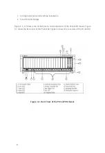
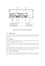
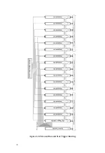
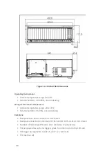
The following figures show the two parts of the backplanes and Mechanical Drawing.
1 2 3 4 5 6
9
sys
3 4 5
7
6
8
1
2
8
7
1
0
1
1
1
2
1
7
1
3
1
6
1
5
1
4
9
11 12 13 14 15 16 17 18
10
Figure B-1 cBX-3018L front view Drawing
R
1
7 6 5 4 3 2
sys
1
3
4
5
6
7
8
2
8
1
4
1
3
1
2
1
1
1
0
9
1
7
1
6
1
5
9
18
11 10
14 13 12
17 16 15
Figure B-2 cBX-3018L rear view Drawing

