7
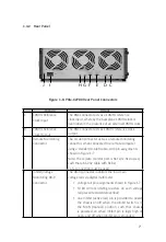
1�4�2 Rear Panel
C
D
E
F
G
H
I
J
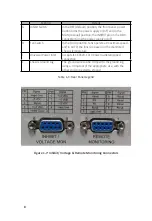
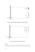
Figure 1-6: PXIe-62780 Rear Panel Connectors
Feature
Details
C
10MHz Reference
Clock Input
The BNC connector acts as a 10MHz reference
clock input, whereby the backplane 10MHz clock is
overridden in the presence of an external 10MHz clock
D
10MHz Reference
Clock Output
The BNC connector acts as 10MHz reference clock
output
E
Remote Monitoring
Connector
The D-sub9 connector acts as a remote monitoring
connector, when connected to a remote computer
using a standard D-sub9 cable, with pin assignments
shown in Figure 1-7
Note: The remote monitor port is Rx-Tx/Tx-Rx crossed,
such that a RS-232 cable with Rx-Rx/
Tx-Tx connection must be used
F
Inhibit/Voltage
Monitoring DB-9
Connector
The DB-9 connector monitors the four main
voltage rails via digital multimeter
• voltage rail pin assignments shown in Figure 1-7
• 10 kΩ current limiting resistors on each voltage
rail prevent accidental overload
• one Inhibit (active low) pin is provided to power
the chassis on/off when the Inhibit Switch is in
the MAN (manual) position, such that chassis
is powered on when Inhibit pin is logic high or
open, and off when Inhibit pin is grounded


