17
rev. C
KB1
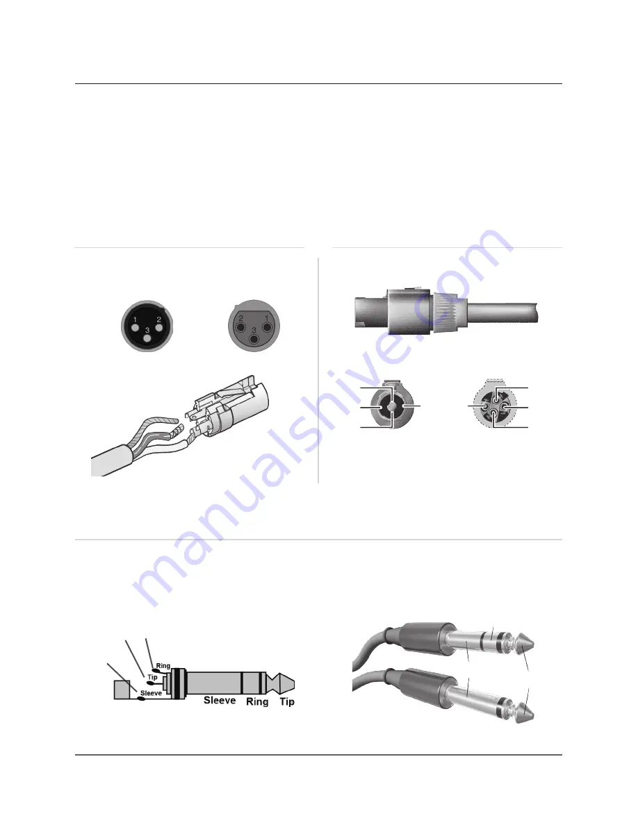
10. AUDIO CONNECTOR WIRING
hot
grd
cold
hot
grd
cold
INPUT
PARALLEL OUTPUT
Balanced Jack
hot
hot
ground
1+
1+
1-
2-
2-
1-
2+
2+
cold
cold
ground
The back panel of the KB1 has different types of audio connector for different
types of entry cable. The following diagrams highlight the different characteristics
of each entry:
XLR wiring
Speakon wiring
CH 1,2 MIC INPUT
CH 2 MIC PARALLEL OUTPUT
MAIN Right OUTPUT / D.I OUT
Jack wiring
Aux OUT
Amplified signal for the top.
4-WIRE speaker cable is required
Summary of Contents for KB1
Page 1: ...KB1 USER MANUAL english version KB1 ...
Page 2: ...KB1 ...
Page 5: ...5 rev C KB1 ...
Page 11: ...11 rev C KB1 7 PHYSICAL 178 220 cm 70 86 32 5 cm 12 8 43 5 cm 17 13 ...
Page 14: ...A B C D F G E H I J K L M N O P S T R U Q V 14 rev C KB1 9 INPUT PANEL OVERVIEW ...
Page 19: ...19 rev C KB1 11 CONFIGURATION OPTIONS AND SET UP ...
Page 20: ...Amplified signal to the TOP AC Power INPUT 20 rev C KB1 ...
Page 21: ...21 rev C KB1 ...
Page 22: ...22 rev C KB1 ...
Page 23: ...23 rev C KB1 ...


