


img. i
i1
i11
i12
i5
i4
i7
i8
i9
i10
i6
i3
i2
38
rev. C
KB1
H8)
L/mono Filter Type Selectors
select the type of filter on the Left Stereo
Output from three options: Low Shelving, Peak/Notch and High Shelving.
H9)
Filter Frequency Knobs
set the central or corner frequency of the
corresponding filter on the Left Stereo Output.
H10)
Filter Gain Knobs
set the gain (positive or negative) of the corresponding
filter on the Left Stereo Output.
H11)
Filter Q / Slope Knobs
set the “Q” or “Slope” value of the corresponding
filter on the Left Stereo Output.
H12)
Filter Graph
shows the effect of the corresponding filter on the signal
frequency spectrum.
H13)
AUX Filter Q / Slope Knobs
set the “Q” or “Slope” value of the
corresponding filter on the Left Stereo Output.
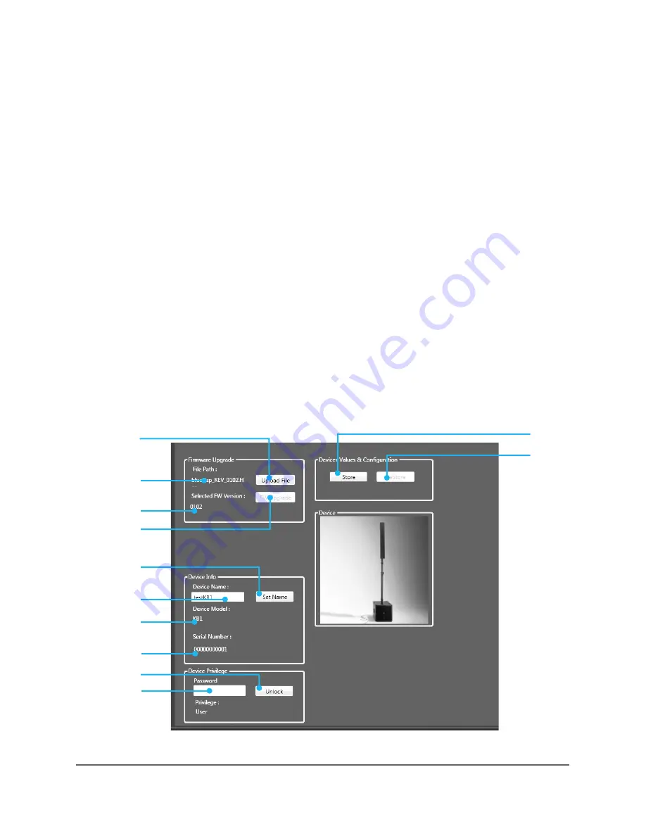
Device Configuration Tab
Summary of Contents for KB1
Page 1: ...KB1 USER MANUAL english version KB1 ...
Page 2: ...KB1 ...
Page 5: ...5 rev C KB1 ...
Page 11: ...11 rev C KB1 7 PHYSICAL 178 220 cm 70 86 32 5 cm 12 8 43 5 cm 17 13 ...
Page 14: ...A B C D F G E H I J K L M N O P S T R U Q V 14 rev C KB1 9 INPUT PANEL OVERVIEW ...
Page 19: ...19 rev C KB1 11 CONFIGURATION OPTIONS AND SET UP ...
Page 20: ...Amplified signal to the TOP AC Power INPUT 20 rev C KB1 ...
Page 21: ...21 rev C KB1 ...
Page 22: ...22 rev C KB1 ...
Page 23: ...23 rev C KB1 ...


