background image

KNX/EIB

Switch Actuator with Secure

23

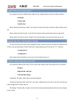
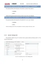
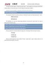
Parameter “Delay for switching on(contact close): --(0...240 minutes) / -- (0...59 seconds)”

This parameter defines the delay time of the switch on (contact close).Options:

0…240 min

0…59 s

Setting the delay time to switch off when object receive the control telegram.

Parameter “Delay for switching off(contact open): --(0...240 minutes) / -- (0...59 seconds)”

This parameter defines the delay time of the switch off.

(contact open).

Options:

0…240 min

0…59 s

During the delay period, if the same packet command is received, the time is reset.
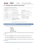
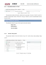
4.4.1.2

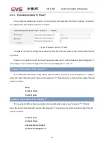
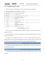
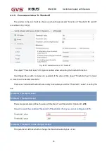
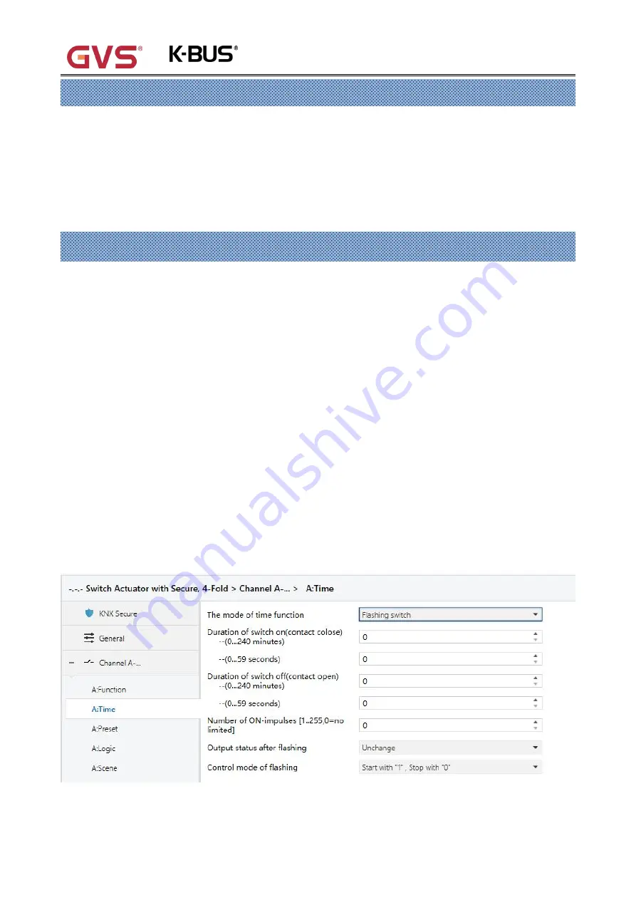
Selection “Flashing switch”

The parameter window in Fig. 4.4.1.2 will be shown up when selecting “Flashing switch” in “The

mode of time function”.

Fig. 4.4.1.2 Parameter window “X: Time”-Flashing switch

Summary of Contents for ARSA-04/16.S

Page 1: ...Switch Actuator with Secure_V1 0 ARSA 04 16 S ARSA 08 16 S ARSA 12 16 S ARSA 04 20 S ARSA 08 20 S ARSA 12 20 S KNX EIB Home and Building Control System User Manual...

Page 2: ...m strong magnetic field high temperature wet environment 2 Please do not fall the device to the ground or make them get hard impact 3 Please do not use wet cloth or volatile reagent to wipe the device...

Page 3: ...Parameter window X Monitoring 44 4 5 2 Parameter window X Forced 46 4 5 3 Parameter window X Regular 47 4 5 4 Parameter window X Safety 48 Chapter 5 Description of communication object 49 5 1 Communic...

Page 4: ...nstall in the distribution boards on 35mm mounting rails according to EN60715 The devices connect to KNX system via bus connection terminal and no additional power supply voltage is required It is abl...

Page 5: ...or with Secure 2 Current and Power measurement Report total current and total power of device Monitoring channel current and total current Switching counter Operation hours counter Inversion of the ou...

Page 6: ...nnections KNX Bus connection terminal 0 8mm Load output connection terminal Screw terminal Cross section 0 2 6 0mm2 Operation and display Programming LED and button For assignment of the physical addr...

Page 7: ...S ARSA 08 20 S 0 60kg ARSA 12 16 S ARSA 12 20 S 0 85kg Product Load type Rated power Life cycles ARSA xx 16 S Incandescent lamp 4000W 30000 xx 04 08 12 Halogen lamp 4000W 5000 Standard Electronic ball...

Page 8: ...lamps in parallel the load will be reduced although the power is unchanged but the instantaneous impact of current will increase and easy to make the relay contacts melted In normal use the maximum o...

Page 9: ...or with Secure 6 Chapter 3 Dimension and Connection Diagram The wiring diagram and dimension drawing of the ARSA xx 20 S are the same with the ARSA xx 16 S 3 1 Dimension ARSA 04 16 S ARSA 04 20 S ARSA...

Page 10: ...KNX EIB Switch Actuator with Secure 7 ARSA 12 16 S ARSA 12 20 S 3 2 Connection Diagram 3 2 1 ARSA 04 16 S ARSA 04 20 S...

Page 11: ...KNX EIB Switch Actuator with Secure 8 3 2 2 ARSA 08 16 S ARSA 08 20 S 3 2 3 ARSA 12 16 S ARSA 12 20 S...

Page 12: ...application layer running normally KNX bus connection terminal Manual operation switch control Output load terminal Reset the device to the factory configuration press the programming button and hold...

Page 13: ...project This will protect the project against unauthorized access The password must be kept in a safe place access to the project is not possible without it not even the KNX Association or device manu...

Page 14: ...added to the selected device in the project as shown in Fig 4 1 4 Fig 4 1 3 Add Device Certificate Fig 4 1 4 Add Device Certificate There is a FDSK sticker on the device which is used for viewing FDS...

Page 15: ...ry settings it is not required if the device is still factory default If it has been used it will be required to reset otherwise the following error message will appear on the right of Fig 4 1 6 and t...

Page 16: ...rted as needed to the use of security keys outside of the associated ETS projects As shown in Fig 4 1 8 below the file extension is knxkeys Fig 4 1 8 Note Any USB interface used for programming a KNX...

Page 17: ...option according to the type of product actually used Options 4 Fold Output apply to ARSA 04 16 S ARSA 04 20 S 8 Fold Output apply to ARSA 08 16 S ARSA 08 20 S 12 Fold output apply to ARSA 12 16 S AR...

Page 18: ...yclically according to the setting to the bus Options 0 240s 0 cyclical send inactive It is suggested to select the maximum time interval according to the application to keep the bus load as low as po...

Page 19: ...x is triggered When the object Safety Priority x x 1 2 is re received the Safety Priority x trigger is ended and the Safety Priority x timing Control period is triggered is reset Options 0 240s If se...

Page 20: ...ator without controller Switch actuator It is used for normal switching for instance lighting control which uses the object Switch to control the output directly Lots of extension functions such as ti...

Page 21: ...s before bus failure When selecting Unchange the contact of the relay will remain the same as the last status before power off When selecting Contact open contact of the channel will be opened when th...

Page 22: ...sible when enabling the logic function Input 0 to define the default value of the communication object Switch after bus voltage recovery which can be 0 or 1 Options To write with 0 To write with 1 Aft...

Page 23: ...en setting 0 contact close 1 contact open while it is open when the value is 1 It means the opposite with setting 0 contact open 1 contact close Parameter Output status for the telegram 1 telegram 0 i...

Page 24: ...ion This parameter defines whether enable the extension functions of the switch actuator The parameter window X Function will be seen when it is enabled and able to set the special functions individua...

Page 25: ...ter window X Function See Fig 4 4 1which is used to enable disable the time function via bus Parameter The Mode Of Time function The parameter defines the type of the timing function setup Options Del...

Page 26: ...e control telegram Parameter Delay for switching off contact open 0 240 minutes 0 59 seconds This parameter defines the delay time of the switch off contact open Options 0 240 min 0 59 s During the de...

Page 27: ...se the output when flashing Options 0 240 min 0 59 s Parameter Duration of switch off contact open 0 240 minutes 0 59 seconds This parameter defines the duration time to switch off contact open the ou...

Page 28: ...g when selecting Star with 0 stop with 1 it will stop flashing with 1 It will start flashing with either 1 or 0 received by the object Switch out with flashing when selecting Star with 1 0 cannot be s...

Page 29: ...meter defines the mode of the staircase lighting function Options Start with 1 OFF with 0 Start with 1 no action with 0 Start with 0 1 cannot be stopped When selecting Start with 1 OFF with 0 it will...

Page 30: ...rovided Via the communication object set the value of the object Warning of staircase as 1 when starting alarming and then send it to the bus Via the output flashing control the output flashing a shor...

Page 31: ...d telegram 1 It means telegram 0 with 0 and telegram 1 with 1 Parameter Output status of the telegram 0 This parameter defines the relay status when recalling the preset value telegram 0 that is when...

Page 32: ...us It is used to set whether changing the preset value by the bus It is allowable to change the value and enable the object Store preset at the same time when enabled which can save the current status...

Page 33: ...t with 0 The value of the communication object Input 1 of logic is logically operated with Switch X firstly and then the result is logically operated with the value of Input 2 of logic This operation...

Page 34: ...value 1 then the logic result of input 0 and input 1 can be output if logic value of the input 2 is 0 the output will keep Options AND OR XOR GATE Below result of logic operation is possible Logic fu...

Page 35: ...ed and the output is directly determined by the input 2 Parameter Invert result if no 1 contact close 0 contact open while yes is opposite This parameter defines whether negate the logical operation r...

Page 36: ...the scene save value during application download If it is disabled the stored values before the download can be not overwritten by the parameterized scene value When the scene is called the scene save...

Page 37: ...per output Options 1 64 0 no allocation Note the valid scene numbers in the parameter setting options are 1 64 The actual corresponding telegram is 0 63 If a scene is stored via a learning telegram th...

Page 38: ...one operation if the value of the object Threshold input is lower or more than the default threshold There are 2 individual thresholds are ready to use always and the Threshold 1 value is set by the...

Page 39: ...e Option Without hysteresis With hysteresis The hysteresis can avoid the unnecessary behaviour caused by the input value if its value is between two threshold values Parameter If falling below lower t...

Page 40: ...ndividually There are 2 safety priorities for every output and also the Safety Priority 2 is prior to Safety Priority 1 It means when these 2 priorities are triggered at the same time the contact posi...

Page 41: ...operation type This parameter defines the data type of the force operation Options 1bit 2bit If selecting 2bit when the object Forced output receives a telegram value the action as follow Value of the...

Page 42: ...t position of the forced operation Options Unchange Contact open Contact close Unchange the contact position is unchanged Contact open the contact position is opened Contact close the contact position...

Page 43: ...Under the 1bit mode it will receive 1 bit command by the communication object On off under the 1byte mode it will receive 1 byte command by the communication object Continuous control 0 means the valv...

Page 44: ...ive is enough after the bus voltage off Parameter If bus recovery valve position is This parameter for setting the action of the valve switch when the bus recovers power supply and the action lasts un...

Page 45: ...d by the room thermostat the relay will undertake an autonomous PWM calculation PWM cycle time is used for this purpose In the control mode of 1 byte the sending value of the room thermostatic control...

Page 46: ...the contact is closed While if it is open it will send 0 to the other devices It is quite the contrary when selecting Yes 0 contact close 1 contact open Note After programmed or system reset if switch...

Page 47: ...c intervals If one or more of the consecutive telegram is omitted this may indicate a communications fault or a room thermostat malfunction During the set monitoring time the switch actuator cannot re...

Page 48: ...ode If enabled when the device does not receive the control value within the monitoring time it will send an error report and this output will perform the dynamic action under the fault mode until it...

Page 49: ...fines the valve position that is triggered by the actuator during the forced operation Options 0 OFF 10 26 90 230 100 ON Unchange Unchange the valve position is unchanged When the forced operation is...

Page 50: ...tatus This function can be started by the object Trigger switch regularly or internally Parameter Time of switch regular in 0 255 This parameter defines the time span when the regular switch carry out...

Page 51: ...fety Priority 1 is triggered at the same time with Safety Priority 2 the contact position will follow the instruction of Safety Priority 2 The priority of the safe operation function is only lower to...

Page 52: ...shown in Table 5 1 Fig 5 1 Communication object General No Function Object name Data type Flags DPT 1 In operation General 1bit C R T 1 001 switch This object is always enabled used to send telegram...

Page 53: ...us which will indicate the contact status details will be defined by parameter Object value of switch status in Channel X The name in parentheses changes with the parameter Description max 30 char If...

Page 54: ...of time function 7 Switch time function Output A 1bit C W 1 003 enable This object will be started when enabling the time function which can be enabled by this object It will enable the timing functio...

Page 55: ...status as the new preset value save the new telegram 0 with 0 and telegram 1 with 1 Table 5 2 3 Preset communication objects 5 2 4 Logic function object of Switch actuator Fig 5 2 4 Logic function co...

Page 56: ...1 64 1 64 in the parameter setup corresponds to the scene number 0 63 received by the communication object Scene handle For example scene 1 in the parameter setup has the same output result as scene...

Page 57: ...e forced function with 1 and the other behaviors will be ignored except the forced function enable the forced function with 0 17 Forced operation Output A 2bit C W 2 001 switch control This object wil...

Page 58: ...This object will be enabled when selecting yes continues control value 1byte in the parameter Reply the status of channel for continuous control indicating the running status of the current valve and...

Page 59: ...thermostat is under malfunction or not It will go into the fault mode with 1 Table 5 3 2 Monitoring communication objects Heating actuator 5 3 3 Forced function object Heating actuator Fig 5 3 3 Forc...

Page 60: ...This object will be visible when enabling the regular switch function to trigger the regular switch Send telegram 1 to turn on the regular switch when the timing time is up to the end of the operatio...

Page 61: ...ty priority 1 Switch Channel special function switch output of time preset logic scene threshold and other functions Dynamic adjustment Forced operation Safety priority 2 Safety priority 1 Switch regu...

Page 62: ...e monitoring time has passed but the operation during the fault cannot be performed and it can only be performed after exiting the high priority operation And during the high priority operation the co...

Reviews: