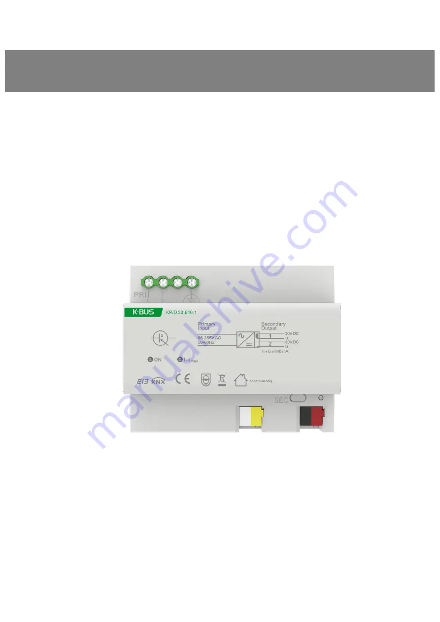
background image

K-BUS

®

Power Supply_V1.1

KP/D 30.640.1

KNX/EIB Home and Building Control System

User Manual

Summary of Contents for KP/D 30.640.1

Page 1: ...K BUS Power Supply_V1 1 KP D 30 640 1 KNX EIB Home and Building Control System User Manual ...

Page 2: ...ces away from strong magnetic field high temperature wet environment 2 Do not fall the device to the ground or make them get hard impact 3 Do not use wet cloth or volatile reagent to wipe the device 4 Do not disassemble the devices ...

Page 3: ...Contents Chapter 1 Introduction 1 Chapter 2 Technical Parameter 2 Chapter 3 Dimension and Connection Diagram 3 3 1 Dimension drawing 3 3 2 Connection Diagram 4 Chapter 4 Normal Working Test 4 ...

Page 4: ...be installed and used according to national wiring rules 7 For indoor use only 8 The product is not a toy keep it where the children can not reach it 9 The power supply are only supply for EIB KNX system equipment with bus line connection terminal 10 Correct Disposal of this product This marking indicates that this product should not be disposed with other household wastes throughout the EU To pre...

Page 5: ...er to facilitate the installation in the distribution box according to the design of EN 60715 it can be installed on a 35mm DIN rail The device is connected with the screw post for electrical connection The bus connection is directly connected through the KNX connection terminal red black The auxiliary power supply is also connected directly through the KNX connection terminal yellow white and the...

Page 6: ...y Green LED ON Output voltage is OK Red LED I Imax Overload or short circuit Reset button SEC Reset at the KNX output starts when the push button is pressed and lasts 22 seconds Red LED Reset at the KNX output Connection Power supply 2 srew terminals Cable cross section Single core 0 2 4 0mm2 Multi core 0 2 2 5mm2 KNX output Bus connection terminal red black Auxiliary voltage output Connection ter...

Page 7: ...K BUS KNX EIB Power Supply 3 Chapter 3 Dimension and Connection Diagram 3 1 Dimension drawing ...

Page 8: ... terminal auxiliary voltage output 5 Mains supply ON Green LED output voltage is OK I Imax Red LED overload short circuit Chapter 4 Normal Working Test When power supply has been correctly installed switch on the main power supply for the bus power and the green LED ON all other LEDs are switched off that is the device function correctly ...

Reviews: