background image

9

(3) Turn the switch ON, and drill a hole in prescribed

depth.

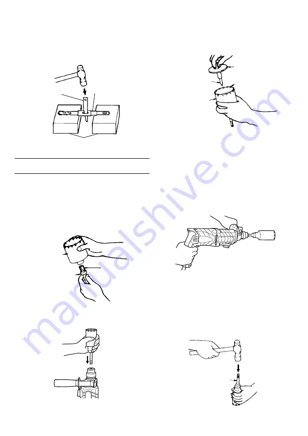
(4) To remove the drill bit (taper shank), insert the cotter

into the slot of the taper shank adapter and strike the
head of the cotter with a hammer supporting on a
rests (Fig. 13).

Fig. 13

HOW TO USE THE CORE BIT
(FOR LIGHT LOAD)

When boring penerating large holes use the core bit (for
light loads). At that time use with the center pin and the
core bit shank provided as optional accessories.
1. Mounting
CAUTION

Be sure to turn power OFF and disconnect the plug
from the receptacle.

(1) Mount the core bit to the core bit shank (Fig. 14).

Lubricate the thread of the core bit shank to facilitate
disassembly.

Fig. 14

(2) Mount the core bit to the rotary hammer (Fig. 15).

Fig. 15

(3) Insert the center pin into the guide plate until it stops.
(4) Engage the guide plate with the core bit, and turn the

guide plate to the left or the right so that it does not
fall even if it faces downward (Fig. 16).

Fig. 16

2. How to bore (Fig. 17)
(1) Connect the plug to the power source.
(2) A spring is installed in the center pin.

Push it lightly to the wall or the floor straight.
Connect the core bit tip flush to the surface and start
operating.

(3) When boring about 5 mm in depth the position of the

hole will be established. Bore after that removing the
center pin and the guide plate from core bit.

(4) Application of excessive force will not only expedite

the work, but will deteriorate the tip edge of the drill
bit, resulting in reduced service life of the rotary
hammer.

Fig. 17

CAUTION

When removing the center pin and the guide plate,
turn OFF the switch and disconnect the plug from the
receptacle.

3. Dismounting (Fig. 18)

Remove the core bit shank from the rotary hammer
and strike the head of the core bit shank strongly two
or three times with a hammer holding the core bit,
then the thread becomes loose and the core bit can
be removed.

Fig. 18

Core bit

Core bit shank

Thread

Tape shank adapter

Cotter

Rest

Core bit

Center pin

Guide plate

Core bit tip

Core bit shank

Summary of Contents for EDH620VRES

Page 1: ...eed and reverse Two mode action rotary and hammer drilling Safety clutch Efficient dust and grease seal design Carrying case with bit storage compartment OPERATOR S MANUAL Please retain this information for future reference WARNING THE SAFETY INFORMATION GIVEN INSIDE MUST BE READ AND UNDERSTOOD BY ANY PERSON USING INSTALLING REPAIRING OR MAINTAINING THESE TOOLS ...

Page 2: ...ts d Remove any adjusting key or wrench before turning the power tool on A wrench or a key left attached to a rotating part of the power tool may result in personal injury e Do not overreach Keep proper footing and balance at all times This enables better control of the power tool in unexpected situations f Dress properly Do not wear loose clothing or jewellery Keep your hair clothing and gloves a...

Page 3: ...ECAUTIONS ON USING ROTARY HAMMER 1 Wear earplugs to protect your ears during operation 2 Do not touch the bit during or immediately after operation The bit becomes very hot during operation and could cause serious burns Drill bit Taper shank Taper shank adapter SDS plus shank Cotter Outer diameter 11 0 mm 12 3 mm 12 7 mm 14 3 mm 14 5 mm 17 5 mm 21 5 mm Taper mode Applicable drill bit Morse taper N...

Page 4: ... W5 16 W3 8 Anchor size W1 4 W5 16 W3 8 W1 2 W5 8 3 Large hole boring rotation hammering 䡬 Center pin core bit core bit shank and guide plate Guide plate Center pin Core bit Core bit shank SDS plus shank Center pin Core bit outer diameter Core bit shank 25 mm 29 mm A 32 mm Core bit shank A Center pin A 35 mm 38 mm 45 mm Center pin B B 50 mm Core bit shank B Do not use core bits with with guide pla...

Page 5: ... Anchor rotation hammering SDS plus shank 12 7 mm Chemical Anchor Adapter 19 mm Chemical Anchor Adapter Standard socket on the market 6 Drilling holes and driving screws rotation only 䡬 Drill chuck chuck adapter G special screw and chuck wrench Chuck adapter G SDS plus shank Chuck wrench Drill chuck 13 VLRB D Special screw ...

Page 6: ...steel or wood 8 Driving Screws rotation only Chuck adapter D SDS plus shank Bit No Screw Size Length No 2 3 5 mm 25 mm No 3 6 8 mm 25 mm 9 Dust cup Dust collector B Optional accessories are subject to change without notice Dust cup Dust collector B 10 Hammer grease A 500 g in a can 70 g in a green tube 30 g in a green tube Bit No Drill chuck 13 VLD D ...

Page 7: ...ch off and disconnect the plug from the receptacle NOTE When using tools such as bull points drill bits etc make sure to use the genuine parts designated by our company 1 Clean the shank portion of the drill bit 2 Insert the drill bit in a twisting manner into the tool holder until it latches itself Fig 1 Fig 1 3 Check the latching by pulling on the drill bit 4 To remove the drill bit fully pull t...

Page 8: ...tch off and disconnect the plug from the receptacle when the drill pits and other various parts are installed or removed The power switch should also be turned off during a work break and after work 1 Switch operation The rotation speed of the drill bit can be controlled steplessly by varying the amount that the trigger switch is pulled Speed is low when the trigger switch is pulled slightly and i...

Page 9: ... screw otherwise the screw head or bit will be damaged or driving force will not be fully transferred to the screw 䡬 Do not attempt to use the rotary hammer in the rotation and striking function with the chuck adapter and bit attached 5 When driving wood screws Fig 10 1 Selecting a suitable driver bit Employ plus head screws if possible since the driver bit easily slips off the heads of minus head...

Page 10: ...ot fall even if it faces downward Fig 16 Fig 16 2 How to bore Fig 17 1 Connect the plug to the power source 2 A spring is installed in the center pin Push it lightly to the wall or the floor straight Connect the core bit tip flush to the surface and start operating 3 When boring about 5 mm in depth the position of the hole will be established Bore after that removing the center pin and the guide p...

Page 11: ...zed Service Center when requesting repair or other maintenance In the operation and maintenance of power tools the safety regulations and standards prescribed in each country must be observed MODIFICATION K EIKO Power Tools are constantly being improved and modified to incorporate the latest technological advancements Accordingly some parts may be changed without prior notice NOTE Due to K EIKO s ...

Page 12: ...11 ...

Page 13: ... 1 38 O RING I D 66 5 1 39 INNER COVER 1 40 PISTON PIN 1 41 WASHER C 2 42 SPACER 1 43 SPRING B 1 44 SECOND SHAFT 1 45 WASHER B 1 46 CLUTCH SPRING 1 47 CLUTCH 1 48 RECIPROCATING BEARING 1 49 FIRST GEAR 1 50 SPACER 1 Item Part Name Q TY No 51 BALL BEARING 626VVC2PS2L 1 52 FELT PACKING 1 53 O RING P 22 1 54 PACKING WASHER 1 55 BALL BEARING 608DDC2PS2L 1 56 WASHER A 2 57 ARMATURE 1 58 FAN GUIDE 1 59 H...

Page 14: ...13 ...

Page 15: ...14 ...

Page 16: ...QUALITY GUARANTEE WARRANTY K EIKO INDUSTRIAL POWER TOOLS carry one years manufacturers warranty K EIKO INDUSTRIAL POWER TOOLS are designed manufactured to the highest standards specifications Assuring the quality and performance required by all sectors of industry K EIKO INDUSTRIAL POWER TOOLS are fully guaranteed against faulty materials workmanship Should they be found to be defective they will ...

Reviews: