Instruction Manual
Section Five
grees toward the cutter center; with a chamfer of 60 degrees from parallel with
the axis of cutter, with simulated peripheral cutting edges; all cutting edges having
only one relief angle of 5 degrees ( for chamfer and face). Instructions are for
non-tilthead grinders unless otherwise noted.
I. SHARPENING THE CUTTER FACE
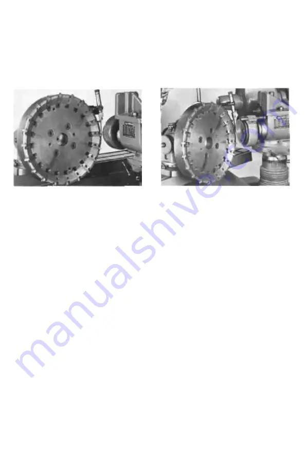
PHOTO 32
PHOTO 33
A. Set-up Preparation;
Place a diamond flared cup wheel or other suitable wheel on the wheel
collet or mounting arbor and attach it to the spindle. Select the proper
wheel speed by use of the correct pulleys and belt Place the axis of the
wheel at a 90-degree angle (OR AT AN 89-DECREE ANCLE IF CLEAR
ANCE IS NEEDED ON OPPOSITE SIDE OF WHEEL) to the table travel
of the machine and with the use of the height gauge, place the wheel cen
ter at the same height as the workhead center (centers of tailstocks may
be used as a gauge for the height of the workhead).
Place large, sensitive workhead at the far right of the swivel table with
its base about 3 inches in from the end Align the workhead base with
the table T-slot by tightening the base plate clamp bar assembly to the
outer edge of the table with the hex socket screw. Tighten the two base
plate T-slot bolts. Turn the correct workhead spindle taper toward the
rear of the machine 'see Photo 32) by loosening the swivel stud nut on
its base and rotating the workhead until the index mark lies at 90 degrees,
Tighten the swivel stud nut Loosen the upper swivel nut on the work
head, tilt the workhead up or down to obtain the desired primary clear
ance angle back of the cutter faces (5 degrees in this instance), and
tighten the upper swivel.
NOTE:
The B992 workhead must be tilted up
ward on all machines; the B9092 may be tilted either up or down. (See
photo 33).
Place the cutter with its milling machine arbor in the workhead and tighten
the draw-bolt assembly. Care must be taken to keep taper surfaces clean
and un-nicked Loosen the clamp bar holding the swivel table at the right
side of the machine and use the table adjusting screw to advance the table
inward at the right so that the pointer at the left side of the table shows
2 degrees. If may be necessary to loosen slightly the center swivel fric
tion locking screw of this fable Tighten the clamp bar.
- 4 4 —


