Instruction Manual
Section Five
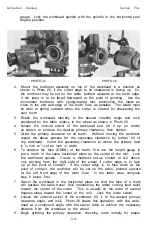
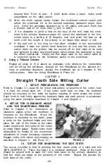
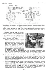
D Mount the universal toothrest on the grinder table, as shown in Photo 37 and
using the micrometer with the spring loaded blade, place it near the back of
the tooth to be ground and lock the hand-nut temporarily. Now reposition
the machine Crossfeed in to a point where the original 0 point was reached.
Do not go beyond this point on the Crossfeed. Adjust the Wheelhead vertically
so that the periphery of the wheel fits near to the bottom of the flute gullet.
If for some reason the 0 Crossfeed position does not allow the face of the tooth
to align flush with the wheel face, there are two possible courses of action:
1. The cutter may have been improperly ground before. This will mean that
the Crossfeed of the machine will have to be adjusted to allow for what
ever rake does exist.
2. If the absolute zero rake is to be maintained, then the wheel will have to
be raised to a point where surface grinding activity can be undertaken to
grind away the rake that does exist.
E. With a tooth face held against the face of the wheel, adjust the toothrest
blade against the back of the tooth high enough so that it can spring upward
and clear the next tooth when the cutter is indexed.
Also, check
to see that
there is some adjustment left in the micrometer screw so the cutter may be
advanced into the wheel as the sharpening proceeds. Tighten the swivel joints
and screws of the toothrest mechanism firmly
F. Move the Crossfeed out
(AWAY FROM THE WHEEL FACE)
slightly and
traverse the table to determine the length of stroke for passing the cutter
under the wheel. The lowest point on the wheel should be passed completely
by the flute gullet. Set a table stop to limit the table travel in one direction.
Start the wheel motor with the cutter to one side and begin a trial run around
the cutter teeth, passing each in succession under the wheel. Continue this
process while advancing the Crossfeed to the 0 point on its dial. From this
point on, all advancement of the cutter faces into the wheel will be accom
plished by adjusting the toothrest micrometer small amounts. This process
rotates the cutter about its axis, thus preserving the radial rake (IF ANY) on
the cutter. During the sharpening process, be sure to hold the cutter firmly
back against the toothrest blade.
C. The
actual grinding process is changed slightly if large amount (on the order
of .020 inch) of stock must be removed in order to create a sharp cutting edge.
In this situation, the grinding wheel should be raised just above the tooth face
after step E. Eliminate step F and traverse the table back and forth holding
the cutter firmly against the toothrest blade and at the same time periodically
lowering the Wheelhead. This results in a surface grinding action which will
cut into the tooth from the top and quickly wear away the excess tooth stock.
H. On the last pass, take a light cut and cover all teeth with this final setting
of
the
micrometer After grinding is completed, the concentricity of the
cutter should be within .0005 inch when checked on the arbor between centers,
II. GRINDING A FORMED CUTTER WITH AXIAL RAKE OR HELIX
Repeat all steps above except A and B which are modified as follows: Instead of
leaving the grinding wheel spindle or motor shaft at a right angle with the table,
rotate either one of the swivels of the Wheelhead the number of degrees required
by the axial rake. This must be done only after placing the wheel face in the ver-
vertica) plane with the
centerline of
the tailstocks. If this angle is not known or
- 5 0 -

