50
Chapter 8 Trouble Shooting
Please follow the list as below for check up. In case of a failure that is impossible to
avoid, please contact your local authorized representative service center for
inspection and maintenance.
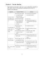
Symptom
Causes of Failure
Solution
The power indicator
will not light up when
power switch turned
on
z
Check if the power supply
cord has been properly
inserted into the AC
receptacle or the MCCB?
z
Check if the fuse broken
z
Check if 4 pin electrical
power cable has been
properly inserted into
4P socket
z
Connect the power plug and the
power adapter properly
z
Replace fuse
z
Properly insert the terminal of 4
pin electrical power cable into 4P
socket
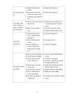
The cylinder does not
up-down when foot
switch (L side)
actives
z
Check if Air source
disconnected
z
Check if pressure is too low
(
<
0.5 Kg/cm²)
z
Check if the speed adjusting
controller of cylinder is
locked
z
Connect the air source。
z
Adjust the pressure up to above 1
Kg/cm²
z
Release the speed adjusting
controller of cylinder
The tooling horn
does not oscillate
z
Check if 10 pin control cable
disconnected
z
Check if upper fuse, on the
rear of generator, broken
z
Check if 2 pin high-voltage
output cable disconnected
z
Properly insert the terminal of 10
pin control cable into 10P control
socket
z
Replace fuse
z
Properly insert the terminal of 2 pin
high-voltage output cable into 2 pin
output socket
Motor speed unable
control
z
Check if 10 pin control cable
disconnected
z
Properly insert the terminal of 10
pin control cable into 10P control
socket
Summary of Contents for KS-2010
Page 12: ...11 ...
Page 13: ...12 ...
Page 22: ...21 ...
Page 23: ...22 ...
Page 31: ...30 6 4 Wiring Diagram A MAIN WIRING DIAGRAM A 1 KS 72 ...
Page 32: ...31 A 2 KS 85 ...
Page 38: ...37 FUSE FUSE B GENERATOR CIRCUIT DIAGRAM KS 72 KS 85 KS 2010 KS 3010 ...


