EN
6
OPTIMA (
pic. 1)
• remove the decorative front panel
• hold the power wire through the cable hole 1 in the case
• strip the insulation on 5-7 mm from the wire end
• insert wires into terminal box X and press them by tap screw
• fix the wires by means of cable clamp 2
• combine clamps of the decorative panel with grooves in the case
• fix the panel with screw
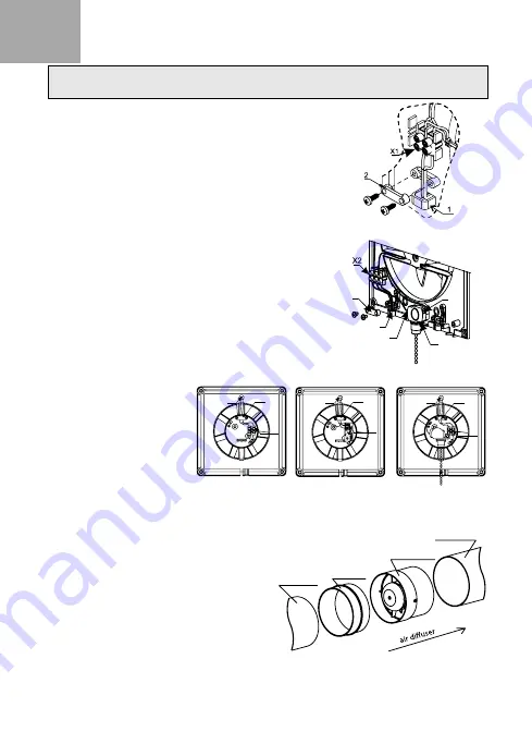
Рic.1 OPTIMA
A / D (pic. 3-5)
• remove the decorative front panel
• hold the power wire through the
cable hole 1 in the case
• strip the insulation on 5-7 mm
from the wire end
• insert wires into terminal box X
and press them by tap screw
• fix the wires by means of cable
clamp 2
• combine clamps of the decorative
panel with grooves in the case
• fix the panel with screw
Рic. 3. A / D
Рic. 4. A / D
Option AT
WIRING DIAGRAM CONNECTION OF AURAMAX FANS TO THE NETWORK
Connection of fan to the network shown in pic. 1-8
Рic. 5. A / D
Option -02
OPTIMA Option -02 (pic. 2)
• remove the decorative front panel
• install S3 switch to the fan case
• connect the wires by inserting the tip pins 3 to the switch S3
• hold the power wire through the cable hole 1 in the case
• strip the insulation on 5-7 mm from the wire end
• insert wires into terminal box X and press them by tap screw
• fix the wires by means of cable clamp 2
• combine clamps of the decorative panel with grooves in the case
• fix the panel with screw
Рic.2 OPTIMA Option -02
S3
1
3
3
2
3
2
1
2
1
3
1
3
2
x
X
VP (pic. 6-8)
• remove the protective cover;
• hold the power wire through the cable hole 1 in the case;
• strip the insulation on 7-8 mm from the wire end
• insert wires into terminal box X and press them by
tap screw
• fix the wires by means of cable clamp 2
• install the protective cover;
Fans of VP series have different diameters of inlet and
outlet pipes for the connection of diffusers with the flange
of the corresponding diameter from absorption and air
ducts from air side discharge.
Рic.6 VP
airvent
airvent
fun
duct
connection


