NOTE: There are no user serviceable
components in this unit. Please return
the unit to K-Tech for repair.
!
INSTALLATION
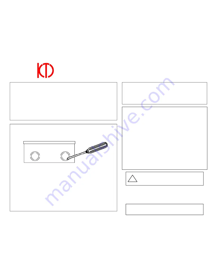
Remove larger 1” knockout(s) with a small tool,
gently
pushing inward from the
outside of enclosure. Shimmy the metal tab back and forth until it completely snaps off.
Push wire through side entry gap of strain relief provided. Adjust wire to desired length.
Snap strain relief into knockout hole from outside the enclosure with slight pressure.
Find a suitable mounting location near the RJ11C type modular jack (within the length
of the included modular cord—12’).
Be sure to locate the unit away from sources
of AC noise such as lighting fixtures, conduits, or an elevator controller.
1. Mount the enclosure on a flat surface using the #10 screws provided.
2. Route the modular cord to the RJ11C type modular jack. Do not connect at this
time.
3. Install the phone(s).
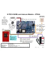
4. Refer to wiring diagram (pg. 2) and make all necessary connections.
5. Plug modular cord into the RJ11C modular jack.
6. Test the system.
RECOMMENDED TELEPHONE LINE SPECIFICATIONS
Line Voltage
24 VDC (±3 VDC) on-hook voltage
Loop Current
30 mA minimum (lower current could cause low volume and
misdialing)
Compatible line types are standard analog, two-wire central office lines from the local
telephone company or some internal PBX system.
The telephone line will be assigned a telephone number which allows the called party
to call back to the dialer and phones. Take care to note this number and supply it to
the called party.
K-TECH SUREcom Intercom Module – ET92A
QUICK GUIDE AND INSTRUCTIONS
TESTING
1.
Press the activating push-button of the emergency phone. Dial
tone will be heard for a few seconds, then automatic dialing will
commence.
2.
After the phone call is connected, pick up the machine room/
lobby phone. The original call should be disconnected and the
intercom module will connect the machine room/lobby phone.
Hang up the machine room/lobby phone, wait 2 seconds, and then
pick up again to confirm it will call back.
Note: If multiple phones on a phone line, be sure to call into each
phone separately. To confirm each phone is programmed
correctly, select the ID code after the greeting message.
Note: Make sure wiring does not interfere with components
and keypad when finalizing installation.
1-800-993-9399
860-489-9399
860-489-4399 (Fax)
K-Tech International
56 Ella Grasso Ave
Torrington CT 06790
Complete warranty and repair information at:
www.KTechOnline.com
WIRING
The incoming telephone line should be terminated with an RJ11
type modular ADA phone wiring should be minimum 20 AWG
twisted/shielded wire if in an area of AC inductance or RF
interference.
Pg. 1


