KTI63505 3 9/12/17
INSPECTION AND SETUP INSTRUCTIONS
Visual inspection should be made before each use of the transmission jack, checking for leaking hydraulic fluid and damaged,
loose or missing parts. Each jack must be inspected by a manufacturer’s repair facility immediately if accidentally subjected to an
abnormal load or shock. Any jack which appears to be damaged in any way, found to be badly worn, or operates abnormally MUST
BE REMOVED FROM SERVICE until necessary repairs are made by a manufacturer’s authorized repair facility. It is recommended that
an annual in spec tion of the jack be made by a manufacturer’s authorized repair facility and that any defective parts, decals or warning
labels be replaced with manufacturer’s specified parts. A list of authorized repair facilities is available from the manufacturer.
Refer to parts breakdown on page 6 and 7:
1. Before using jack for the first time, some assembly is required. Place hydraulic unit in upright position and bolt legs (#R30) to base
(#R38) using bolts (#R34) and washers (#R32 and R33).
2. Assemble each caster to leg using washers (#R36) and nuts (#R35).
3. Attach fingers (#2) to plate (#3) using bolts (#1), washers (#4), and wing nuts (#5).
AIR BLEEDING INSTRUCTIONS
IMPORTANT!
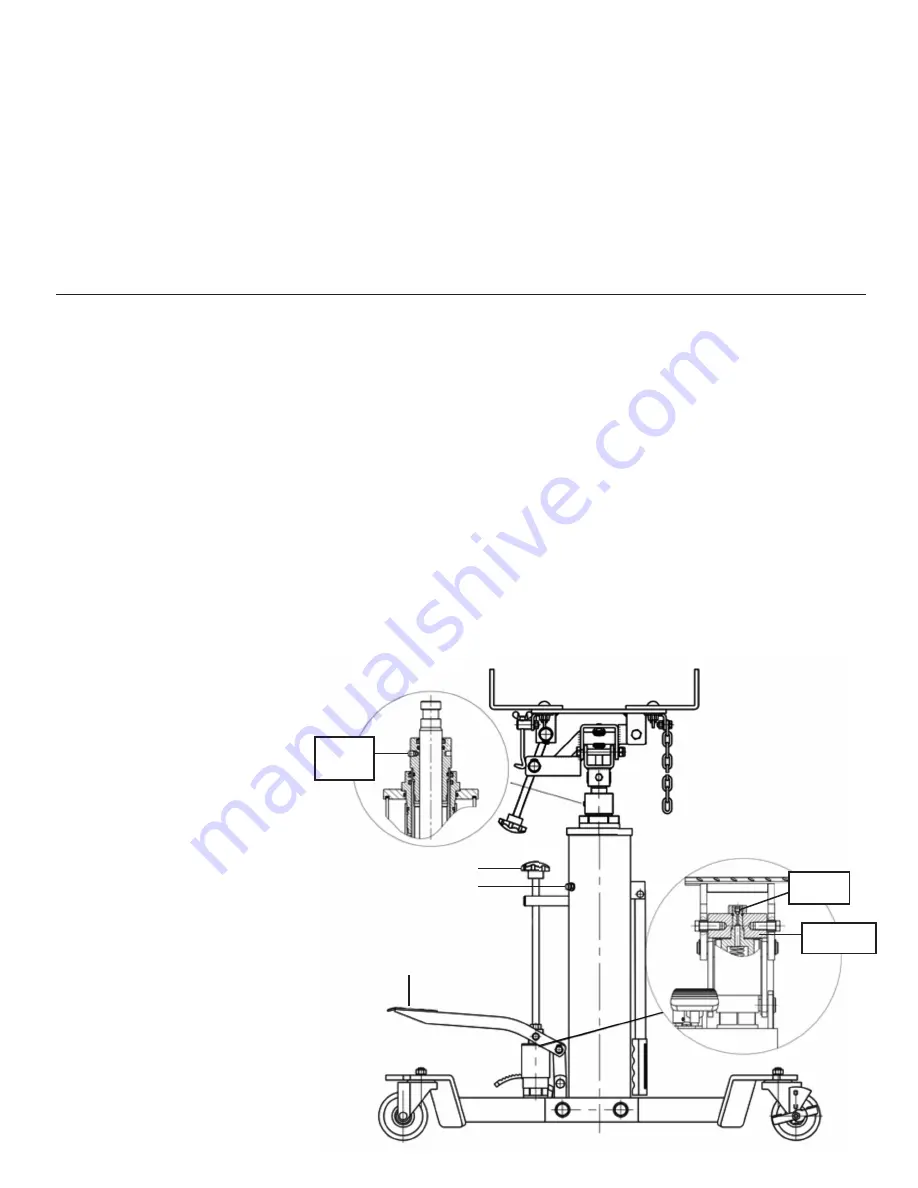
If the transmission jack is not able to raise the load, or raises it very slowly, there may be air trapped in the hydraulic
system. Follow these instructions and refer to Diagram 1 and parts page 7:
1. Turn the air vent screw (#R23) counterclockwise until it stops.
2. With both rams in their lowered position, turn the release knob (#R50) clockwise until it stops.
3. Loosen but do not remove the M6 x 5 inner Allen socket screw (#R52) by turning it counterclockwise two revolutions.
4. Pump the foot pedal (#R44) 2 or 3 times until you see oil coming out of the M6 x 5 Allen socket screw hole.
5. After 3 foot pumps, hold the pedal (#R44) down while simultaneously turning the M6 x 5 Allen socket screw (#R52) clockwise
until tight.
6. Activate the pedal (#R44) to see if the jack can raise smoothly. If not, repeat steps #2 through #5 again.
If the transmission jack can raise a load but its rams are not traveling smoothly, there may be air trapped in the rams that need to be
bled as follows:
1. Turn the release valve knob (#R50) clockwise until it stops. Activate the foot pedal (#R44) until both rams are fully extended.
2. Turn the M8 x 10 BLEED SCREW (#R14) counterclockwise 1 to 1.5 revolutions, pump the foot pedal (#R44) 2 to 3 times until oil
comes out of the M8 x 10 BLEED SCREW hole.
3. Turn the M8 x 10 BLEED SCREW (#R14) clockwise until tight.
4. Turn the release valve knob (#R50) in a counterclockwise
direction to lower both rams all the way down. Turn
the release valve knob (#R50) clockwise until it
stops and pump the jack to maximum height.
Operate the jack up and down
once again to see if the rams
are responding properly. If better
but not complete, repeat steps
#1 through #4 again.
M6 x 5
SCREW
M8 x 10
BLEED
SCREW
DIAGRAM 1
R50
R23
BLOCK
OF STEEL
R44


