WinKey USB SMT Assembly and Operation Guide - Version 1.5 12/26/2017 Pg 3
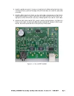
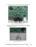
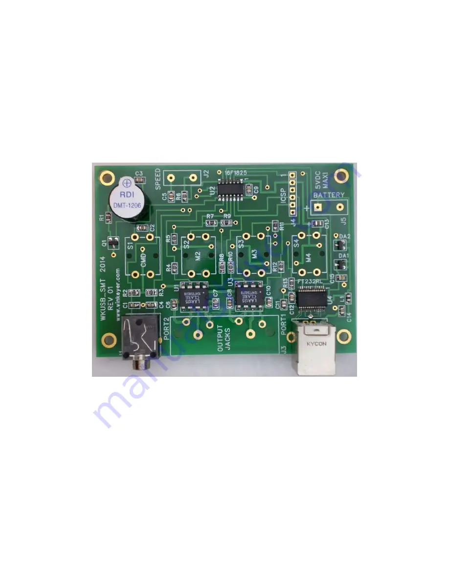
3) Install the paddle connector J1, make sure it sits flat on the PCB and that the front of the
connector is lined up with the front edge of the PC board. Be sure to hold it in place while
you solder.
4) Install the USB connector J6. Bend over the holding tabs and make sure it is flush to the
board before soldering. It helps to tack solder one of the tabs first to hold it in place. The
signal pins on this connector are very easy to bridge together if you use too much solder.
5) Install and solder piezo speaker SP1, observe polarity and align s to silk
There are four holes, two pairs with different spacing. Rotate the speaker to find the pair
that fits. Peel off the protective film covering the top of the speaker.
Figure 2 – J1, J6, and SP1 installed


