WinKey USB SMT Assembly and Operation Guide - Version 1.5 12/26/2017 Pg 8
Kit Checkout
Warning: Please do not use WKUSB3 with the WK2CFGMAC application or with Ham
Radio Deluxe (HRD/DM780) releases earlier than 6.2.
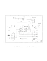
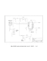
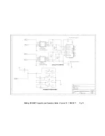
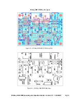
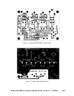
Winkeyer USB PCB schematics are on pages 12, 13, & 14. It is a fairly simple design. There are
two ICs, a WK3 PIC microcontroller and a FT232RL USB interface. The WK3 PIC is powered
either from a 4.5V battery pack or USB port. Two diodes select the active supply. When WKUSB
is plugged into a USB port, the internal battery pack is electrically disconnected. (Never use a
battery supply greater than 5V) To insure that the power down mode current is as small as
possible, a voltage regulator is not utilized. The WK3 PIC is USB compliant in that it will go into a
power down mode when the USB port goes into standby. The WK3 PIC monitors USB status by
checking the FT232RL’s SLEEP output pin.
The WKUSB keyer has two modes, host mode and standalone mode. In host mode, WKUSB is
connected to a PC which has issued an open command from a running application. If WKUSB is
connected to a host but the host has not issued an open command, WKUSB will stay in
standalone mode. In standalone mode, WKUSB will operate as a full featured keyer with
message pushbuttons and a Morse command interface. In host mode WKUSB is under control of
the PC and will not respond to pushbutton commands.
The WKUSB-SMT circuit board is assembled and tested at the factory so it should work on first power
up. As a first test, install three AAA batteries and WKUSB should come alive and send an ‘R’ on the
sidetone speaker. You should get an MT when you press each message pushbutton, this signifies
that the messages slots are e
M
p
T
y. Now press and hold the red pushbutton and after a few seconds
WKUSB will respond with a R. Release the button and after a few more seconds it will send a
question mark. If you have a paddle set handy, plug it in and check that WKUSB will send dits and
dahs. Turning the speed pot will change the WPM rate. The keyer initially starts in standalone mode
so you can enter paddle commands. Read the standalone keyer section of the WKUSB manual for
complete information on entering commands.
Now for host mode testing, we have to consider a USB driver. This is we are going to switch over
to the WKUSB User Guide which has lots of information about host mode interfacing.
Initial startup issues that you may encounter:
WKUSB does not send an R when powered up:
Measure the voltage between pin 1 and 14 on the WK3 IC. You should see about 4.0 volts or one
diode drop less than the battery voltage. It’s possible that the WK3 IC is functioning but the sidetone
speaker circuit is at fault. Look for missing or marginal solder connections.
WKUSB is not responding to paddle input or is sending out a continuous series of dits or
dahs:
Check the paddle cabling, J1, and associated input circuit for shorts or opens.
WKUSB periodically sends out an R followed by a ? or an MT,
you probably have a problem with
the 2.2K pushbutton network (R5, R7, R9, and R11).
WKUSB is completely unresponsive or just sends a single dit on power up:
this can be caused
by a missing or miswired speed pot.
WKUSB responds to command pushbutton press with an L instead of an R:
Low battery voltage
WKUSB
sends
an initial R but then is completely unresponsive:
One of the paddle inputs are
stuck low, this can be caused by a solder short, bad paddle cable, or you used a solder with organic
flux which can be conductive. Carefully wash excess flux off the board.


