CLEAR
THROUGH
FIREWALL
BLACK
RUBBER
GROMMET
TO VEHICLE
INTERIOR
BLACK
CLEAR
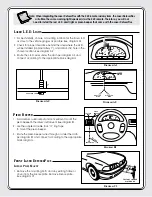
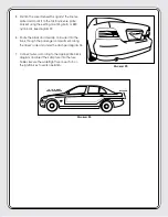
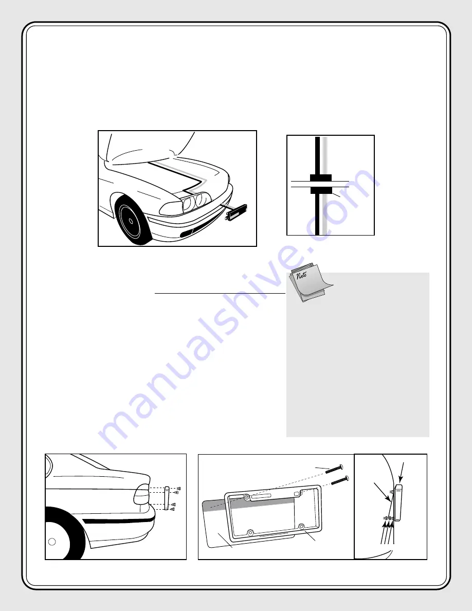
6. Route the black and clear zip cord wires into the engine compartment either through the grill or under the
bumper. See diagram D6.
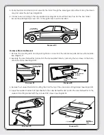
7. Pass both the black and clear zip cord wires towards the vehicle’s firewall and through an existing rubber
grommet into the vehicle’s cockpit. See diagram D7.
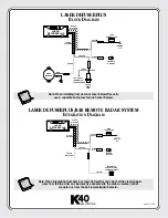
8. Connect wires according to the appropriate block diagram and insert the 3amp fuse into the fuse holder.
Secure the watertight fuse cover. Turn on the ignition key to verify operation.
D
IAGRAM
D6
D
IAGRAM
D7
R
EAR
L
ASER
D
EFUSER
P
LUS
L
ICENSE
P
LATE
M
OUNT
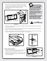
1. Remove the mounting bolts and any existing frame or cover
from the rear license plate. Remove license plate.
See diagram E1.
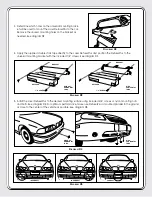
2. Position the Laser DefuserPlus around the existing rear license
plate and mount it against the factory license plate bracket.
Use the existing mounting bolts or K40 nylon bolts to secure
the DefuserPlus frame and license plate to the bracket.
See diagram E2.
D
IAGRAM
E2
FACTORY LICENSE
PLATE BOLTS
D
IAGRAM
E1
Note: For optimum per-
formance, the DefuserPlus
must be mounted parallel to
the ground. Use the supplied K40
nylon nuts and bolts to correct the
mounting angle of the DefuserPlus
either up or down as needed.
On some vehicles, it may be necessary
to adjust or reposition the factory
license plate bracket to achieve the
parallel mounting.
On vehicles that have only one set of
bracket mounting holes, it is recom-
mended that the Laser DefuserPlus
and the license plate be bolted
together to eliminate any vibration.
LICENSE
PLATE
LICENSE PLATE
LASER DEFUSERPLUS
BOLTS
DEFUSERPLUS
FACTORY
MOUNTING
LOCATION
MOUNTING NUTS


