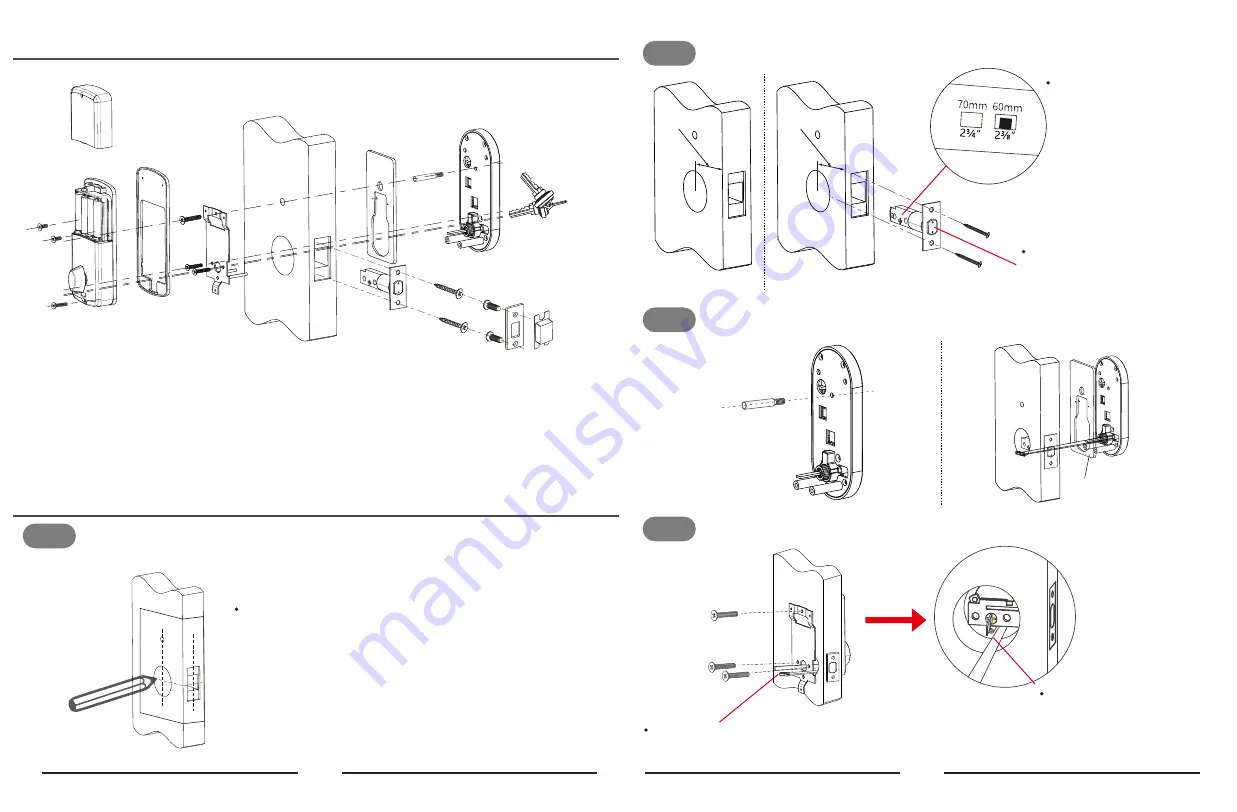
Step 1
Installation Diagram
Installation Diagram
According to the map drilling holes on the door.
Note:
1) Check the required backset (60mm or 70mm).
2) Align the template along the vertical center
line of the deadbolt(E) at the desired height,and
tape it to the door.
3) Mark the holes first, then start drilling.
A) Outdoor lock body * 1
B) Silicon gasket * 1
C) Mounting plate * 1
D) Indoor lock body * 1
E) Deadbolt * 1
F) Cylindrical sleeve bolt * 1
G) M4 x 25mm cross flat head bolt *1
H) M4 x 30mm cross flat head bolt * 3
I) M4 x 10mm cross flat head bolt * 2
J) M4 x 25mm cross flat head self-tapping screw * 4
K) Mechanical key * 2
L) Strike plate * 1
M) Latch holding plastic box * 1
02
03
G
D
I
K
C
B
J
F
M
L
H
E
A
Step 2
Install the deadbolt (E) with screws (J) on the door.
Step 3
Install outdoor unit(A) with cylindrical sleeve bolt(F)and gasket(B) on outdoor unit(A).
Step 4
Install mounting plate (C) with M4 cross flat head bolt (H) on the door.
Note: DO NOT Push the latch
out before installation.
J
E
Note: Cable goes
underneath deadbolt.
C
H
Note: The cable goes through the notch on the
lower right part of the mounting plate at first.
Note:
The deadbolt has TWO
backset options: 70mm or
60mm, please adjust it by
yourself.
F
A
B
2⅜”(60mm)
2¾”(70mm)


